
System for automatically monitoring states of gate valves and Shutters

An automatic monitoring and plug-in valve technology, applied in valve devices, voltage-only measuring devices, and other directions, can solve problems that are prone to accidents and secondary problems, cannot be quickly located and solved, and hidden safety hazards, and achieve fast installation and maintenance. Simple structure and high safety effect

Pending Publication Date: 2020-09-29
HEFEI INSTITUTES OF PHYSICAL SCIENCE - CHINESE ACAD OF SCI +1
View PDF0 Cites 0 Cited by
  • Summary
  • Abstract
  • Description
  • Claims
  • Application Information

AI Technical Summary

Problems solved by technology

The staff cannot observe in real time with the naked eye, nor can they control the site manually. They often cannot understand and accurately record the status of the flapper valve or Shutter in time, which is likely to cause accidents and secondary problems; for those who install multiple flapper valves or Shutters Even if there is a problem with the device or equipment, it cannot be quickly located and solved, which will cause great inconvenience and safety hazards

Method used


Image

  • System for automatically monitoring states of gate valves and Shutters
  • System for automatically monitoring states of gate valves and Shutters
  • System for automatically monitoring states of gate valves and Shutters

Examples


Embodiment 1

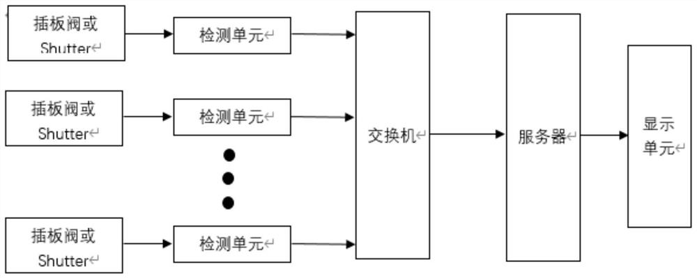
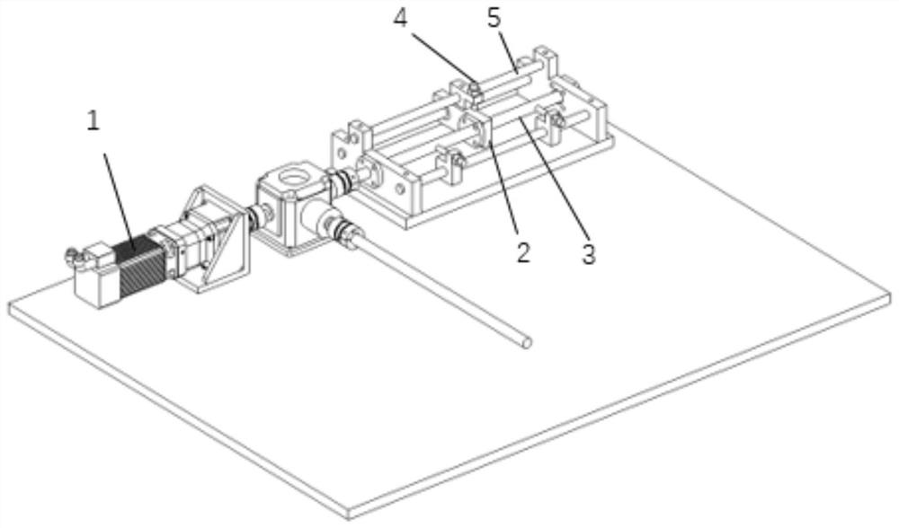
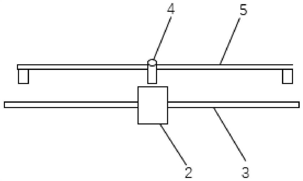
[0032] Example 1, figure 1 is a structural schematic diagram of the present invention; figure 2 It is a schematic structural diagram of using the proximity switch method to collect state data in the present invention; image 3 It is a structural schematic diagram of a proximity switch and a displacement slider of the present invention; Figure 4 It is a structural schematic diagram of the voltage detection module of the present invention.

[0033] see Figure 1-Figure 4 As shown, a system for automatically monitoring the status of the gate valve and the Shutter, including a multi-channel detection unit, a switch, a server, and a display unit;

[0034] The detection unit detection includes a plurality of state acquisition modules and a lower computer, which are used to simultaneously detect the status signals of a plurality of flapper valves or Shutters, and the codes are sent to the switch connected to it after the lower computer summarizes and analyzes;

[0035] The flap...


PUM


Abstract

The invention discloses a system for automatically monitoring the states of gate valves and Shutters. The system for automatically monitoring the states of the gate valves and the Shutters comprises amulti-path detection unit, a switch, a server and a display unit, the multi-path detection unit comprises a plurality of state acquisition modules and a lower computer; the state acquisition modulesare displacement detection units or voltage detection units, the lower computer comprises a single-chip microcomputer unit which is used for receiving information of the state acquisition modules, analyzing and processing the information, coding the information and sending the information to the switch; the switch is used for receiving coded information from the lower computer and sending the coded information to the server; the server is used for receiving data sent by the switch and storing the data in a local database; and the display unit is a webpage constructed by adopting a B / S structure and is used for reading the database and displaying the state information of each gate valve or Shutter. The system for automatically monitoring the states of the gate valves and the Shutters can monitor the states of the gate valves and the Shutters in real time and upload the state data to the server for storage and display so that workers can inquire the state data at any time, and the systemhas the advantages of being convenient to use, low in delay and high in safety.

Description

technical field [0001] The invention relates to the technical field of gate valve and shutter control, in particular to a system for automatically monitoring the state of gate valve and shutter. Background technique [0002] The flapper valve is also known as the sealing knife gate valve. The sealing knife gate valve is a kind of valve in which the gate and the valve seat are always in close contact and sealed. The opening and closing of the ram makes the round opening on the ram completely separate from and coincide with the diameter. The advantage of this valve is that there is no groove in the bore of the valve body, the medium will not be blocked and blocked, and it has full-bore flow characteristics. Its sealing structure can be divided into soft seal and hard seal structure. The gate valve includes electric gate valve and pneumatic gate valve. The electric gate valve is driven by the motor to push the gate forward or backward to realize the opening or closing of the ...

Claims


Application Information

Patent Timeline
Patent Type & Authority Applications(China)
IPC IPC(8): F16K37/00G01B21/02G01R19/00
CPCF16K37/0075G01R19/0084G01B21/02
Inventor 扈嘉辉赵君煜臧庆韩效锋胡爱兰肖树妹
Owner HEFEI INSTITUTES OF PHYSICAL SCIENCE - CHINESE ACAD OF SCI
Learn More