
Current sensor

A current sensor and sensor technology, which is applied in the direction of only measuring current, electric solid devices, voltage/current isolation, etc., can solve the problems of expensive design and processing, and achieve breakdown strength, reduce the chance of accidental contact, and high breakdown strength Effect

Pending Publication Date: 2020-09-29
メレクシステクノロジーズソシエテアノニム
View PDF1 Cites 2 Cited by
  • Summary
  • Abstract
  • Description
  • Claims
  • Application Information

AI Technical Summary

Problems solved by technology

EP3333580 provides connectivity via CMOS, but usually requires special design and expensive processing

Method used


Image

  • Current sensor
  • Current sensor
  • Current sensor

Examples


Embodiment Construction

[0054] The present invention will be described with respect to particular embodiments and with reference to certain drawings but the invention is not limited thereto but only by the claims. The dimensions and relative dimensions do not correspond to actual reductions to the present invention.

[0055] Furthermore, the terms first, second, etc. in the description and claims are used to distinguish between similar elements, and not necessarily to describe an order in time, space, rank or any other way . It is to be understood that the terms so used are interchangeable under appropriate circumstances and that the embodiments of the invention described herein are capable of operation in other sequences than described or illustrated herein.

[0056] In addition, the terms top, bottom, etc. in the description and claims are used for descriptive purposes and not necessarily for describing relative positions. It is to be understood that the terms so used are interchangeable under ap...


PUM


Abstract

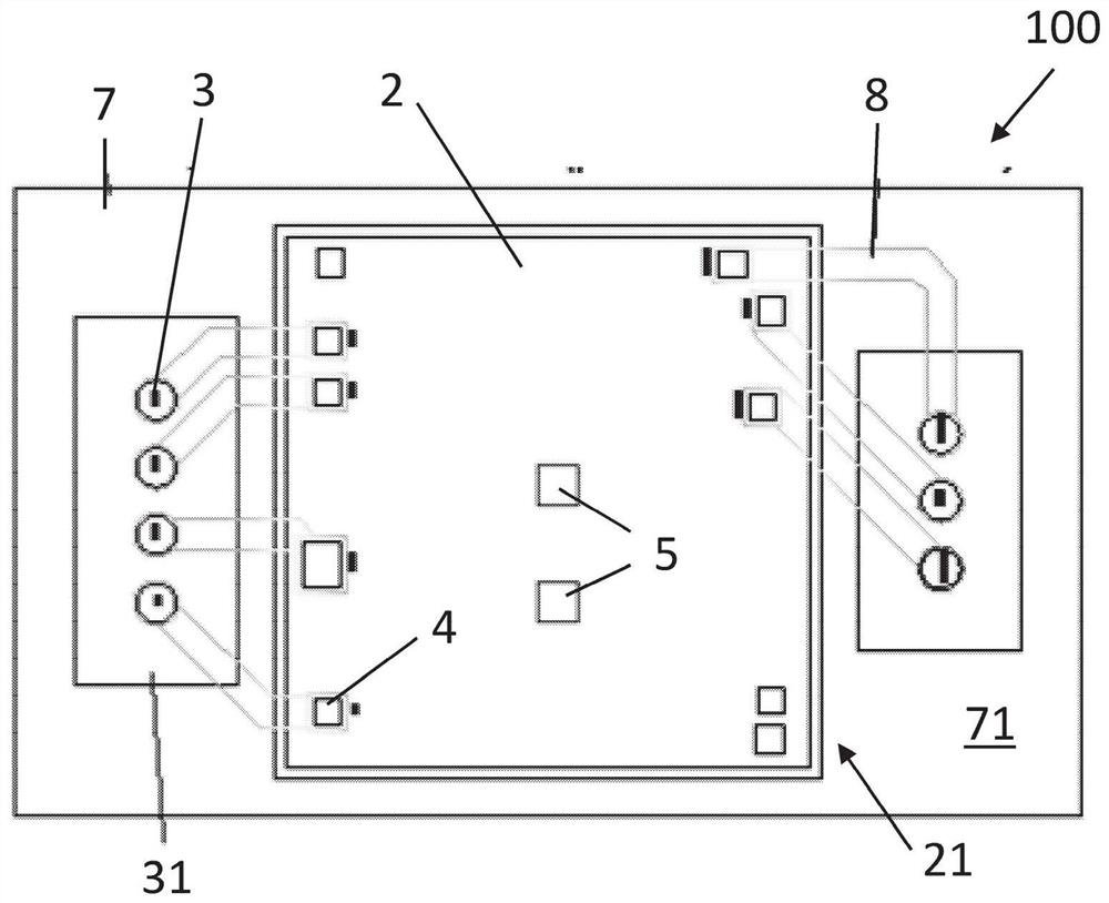
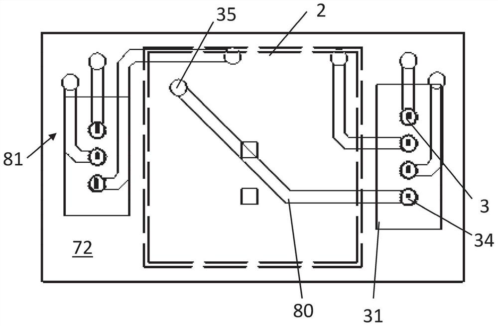
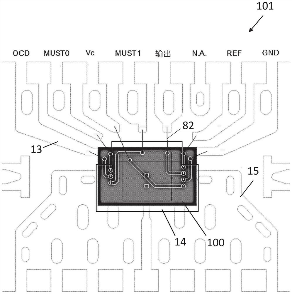
A current sensor (101) is described and comprises an integrated circuit (2) for sensing electric currents, the integrated circuit (2) comprises an active side (21), and the active side comprises at least one sensing element (5) and at least one contact pad (4) and a housing (7) comprising material embedding the integrated circuit (2) and arranged for allowing electric connection to the at least two contact pads (4) of the active side of the integrated circuit (2). The housing comprises at least one conductive via (3) disposed outside the integrated circuit (2) and connected to the at least onecontact pad (4), for distributing signals from the at least one contact pad (4) through the housing (7) away from the active side (21) of the integrated circuit (2).

Description

technical field [0001] The invention relates to the field of electrical sensors. More specifically, it relates to an integrated current sensor with high-voltage isolation characteristics and its fabrication method. Background technique [0002] Current sensing, eg for controlling operation, is necessary in many applications such as eg solar cell inverters, car batteries, servo drives, electric bicycles, etc. It is often important to provide current sensors in a compact manner. One way to obtain a compact current sensor is by integrating the current sensor into the electronics. In such configurations, there is typically a lead frame and an integrated circuit or chip (such as a semiconductor chip) mounted on the lead frame. A chip, which typically may be an integrated circuit (IC) with a Hall plate element, acts as a sensor when it is used in conjunction with a current-carrying conductor allowing a magnetic field to be generated. Typically, there may be electronics for sen...

Claims


Application Information

Patent Timeline
Patent Type & Authority Applications(China)
IPC IPC(8): G01R19/00G01R15/20
CPCG01R19/0092G01R15/202G01R15/207H01L21/4825H01L21/565H01L21/76898H01L23/4952H01L23/49541H01L24/05H01L24/48H01L2224/05554H01L2224/48091H01L2224/48247
Inventor T·万格文A·J·范德维尔
Owner メレクシステクノロジーズソシエテアノニム
Learn More