Method and device for testing XPIC performance of microwave transmission equipment
A microwave transmission and performance technology, applied in the field of communication, can solve problems such as lack of technology, and achieve the effect of simple test device and safe and reliable test results
- Summary
- Abstract
- Description
- Claims
- Application Information
AI Technical Summary
Problems solved by technology
Method used
Image
Examples
Embodiment 1
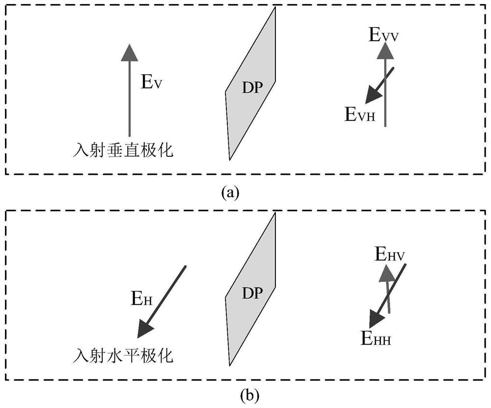
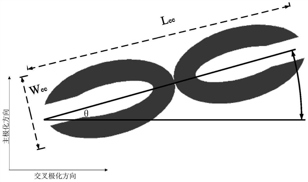
[0074] First follow image 3 The simulation modeling of the pass-through polarization degraded board is carried out. In the simulation model, the base material of the printed circuit board is FR4 material, and the simulation is carried out by using the finite difference time domain method. The incident polarization is as follows: figure 2 In the main polarization direction, the depolarization effect is defined as the "electromagnetic field cross-polarization degeneration ratio" parameter such as figure 1 Medium electric field strength E VH and E VV ratio, where E VH and E VV Both take the root mean square value on the simulation plane. And set different angles between the unit axis and the cross isolation direction in the simulation, and observe the changes of the parameters. Simulation results such as Figure 7 shown. It can be seen that from 15 GHz to 85 GHz, all have polarization degradation characteristics, that is, have broadband characteristics, and the setting o...
Embodiment 2
[0076] First follow Figure 8 Carry out the simulation modeling of the pass-through polarization degraded plate. In the simulation model, the base material of the printed circuit board is FR4 material. This is a relatively simple periodic structure arrangement of elliptical units. The ratio of the major axis to the minor axis of the ellipse is 4 : 1, the length of the minor axis is 0.25 times the wavelength of the applicable operating frequency, the simulation is performed using the finite difference time domain method, the incident polarization is vertical polarization, and different angles between the unit axis and the cross isolation direction are set in the simulation, and the observation parameter changes. The simulation results of "Vertical Polarization Coupling Interference Ratio" are as follows: Figure 9 shown. It can be seen that from 15 GHz to 85 GHz, all have polarization degradation characteristics, that is, have broadband characteristics, and the setting of the...
PUM
 Abstract
Description
Claims
Application Information
 - R&D
- Intellectual Property
- Life Sciences
- Materials
- Tech Scout
- Unparalleled Data Quality
- Higher Quality Content
- 60% Fewer Hallucinations
Browse by: Latest US Patents, China's latest patents, Technical Efficacy Thesaurus, Application Domain, Technology Topic, Popular Technical Reports.
© 2025 PatSnap. All rights reserved.Legal|Privacy policy|Modern Slavery Act Transparency Statement|Sitemap|About US| Contact US: help@patsnap.com


