
Heat accumulating type electric heating high-temperature electrode leading-out device

A technology of electrode extraction and electric heating, applied in the direction of ohmic resistance electrodes, ohmic resistance heating parts, etc., can solve the problems of high temperature aging of seals, poor cooling effect, hidden safety hazards, etc., achieve stable sealing performance and increase installation space , the effect of meeting the requirements of use

Pending Publication Date: 2020-09-29
WUXI HENGYE ELECTRICAL HEATER EQUIP +1
View PDF0 Cites 0 Cited by
  • Summary
  • Abstract
  • Description
  • Claims
  • Application Information

AI Technical Summary

Problems solved by technology

[0003] In the prior art, it is necessary to lead out the power supply from the pressure vessel of the electric heater, usually directly using a solid electrode to lead out. In order to improve the current carrying capacity of the electrode, the usual method is to use low-resistivity materials or increase the current flow cross-sectional area, but the thermal conductivity of low-resistivity metal materials is high, and the increase in electrode cross-sectional area is equivalent to the increase in heat transfer area, which directly leads to the increase in heat transfer in high-temperature environments, so conventional electrode structures cannot achieve high-temperature environments. For the purpose of large current transmission, when external water cooling is used, it is difficult to achieve efficient cooling requirements due to the small surface area of ​​the solid structure for cooling. At the same time, the poor cooling effect will cause high-temperature aging of the seals, and there are certain safety hazards. Meet the use requirements

Method used


Image

  • Heat accumulating type electric heating high-temperature electrode leading-out device
  • Heat accumulating type electric heating high-temperature electrode leading-out device
  • Heat accumulating type electric heating high-temperature electrode leading-out device

Examples


Embodiment Construction

[0037] The specific implementation manner of the present invention will be described below in conjunction with the accompanying drawings.

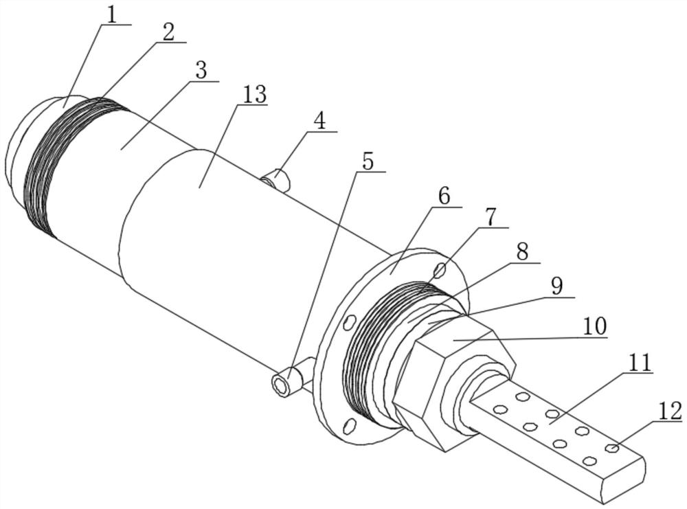
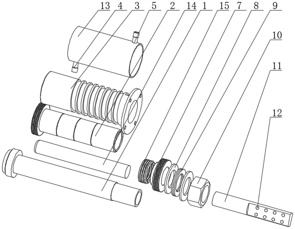
[0038] Such as Figure 1-Figure 7 As shown, the regenerative electric heating high-temperature electrode lead-out device of this embodiment includes an electrode lead-out section 1. A cavity 104 with a "U"-shaped cross section is opened in the middle of the electrode lead-out section 1, and the cavity 104 is filled with ceramics. Fiber heat insulation cotton 14, the electrode connection section 11 is installed in cooperation with the tail of the cavity 104 filled with ceramic fiber heat insulation cotton 14;

[0039] The outer peripheral surface of the electrode lead-out section 1 is fitted with a first insulating ceramic 2, and the electrode lead-out section 1 at the tail of the first insulating ceramic 2 is sequentially covered with a V-shaped sealing ring 15 and a second insulating ceramic 7, the first insulating ceramic 2 and The oute...


PUM


Abstract

The invention provides a heat accumulating type electric heating high-temperature electrode leading-out device which comprises an electrode leading-out section, a cavity with a U-shaped section is formed in the middle of the electrode leading-out section, the cavity is filled with ceramic fiber heat insulation cotton, and then an electrode wiring section is installed. First insulating ceramic is mounted on the outer circumferential surface of the electrode lead-out section in a matched manner; an electrode leading-out section at the tail part of the first insulating ceramic is sequentially sleeved with a V-shaped sealing ring and a second insulating ceramic; the outer circumferential surfaces of the first insulating ceramic and the second insulating ceramic are simultaneously provided witha spiral channel type water cooling jacket, the outer circumferential surfaces of the spiral channel type water cooling jackets are sleeved with a shell, and the shell is provided with a cooling water outlet and a cooling water inlet which are communicated with the spiral channel type water cooling jackets; flat gaskets are arranged on the electrode leading-out section on the outer side of the second insulating ceramic at intervals, a disc spring is arranged between the two flat gaskets, and compression nuts are arranged outside the flat gaskets on the outer sides. The structure is reliable in performance, and the use requirements of special occasions such as high-temperature environments and high-current-density transmission can be met.

Description

technical field [0001] The invention relates to the technical field of electrode lead-out devices, in particular to a regenerative electric heating high-temperature electrode lead-out device. Background technique [0002] The electric heater is a core electric heating equipment for technology research and development and performance verification of key military equipment. It is used for heating the flowing gaseous medium. When the heating medium passes through the heating chamber of the electric heater under pressure, the principle of fluid thermodynamics is used to uniformly take away the huge heat generated in the internal work of the electric heating element, so that the temperature of the heated medium meets the process requirements. [0003] In the prior art, it is necessary to lead out the power supply from the pressure vessel of the electric heater, usually directly using a solid electrode to lead out. In order to improve the current carrying capacity of the electrod...

Claims


Application Information

Patent Timeline
Patent Type & Authority Applications(China)
IPC IPC(8): H05B3/03
CPCH05B3/03
Inventor 赵钧辛亚楠高亮洁王春花赵成旺
Owner WUXI HENGYE ELECTRICAL HEATER EQUIP
Learn More