
Machine table of filter press

A filter press and machine technology, which is applied in filtration separation, separation methods, chemical instruments and methods, etc., can solve the problems of the simple machine of the filter press, the pollution of the filter plate washing water, the separation of the filter plate washing water, etc. problems, to achieve the effect of facilitating transportation, strengthening support strength, and strengthening support stability

Inactive Publication Date: 2020-10-02
广东忠能科技集团有限公司
View PDF0 Cites 0 Cited by
  • Summary
  • Abstract
  • Description
  • Claims
  • Application Information

AI Technical Summary

Problems solved by technology

[0004] The machine structure of the filter press in the prior art is too simple. The filter press is directly installed in the water receiving tank. Although it is convenient to collect filtered water, it is not convenient to separate the filter plate washing water, so that the collection of filtered purified water If it is not pure, it will be polluted by the washing water of the filter plate, and the machine of the filter press is too simple and the support strength is poor

Method used


Image

  • Machine table of filter press
  • Machine table of filter press
  • Machine table of filter press

Examples


Embodiment Construction

[0018] The technical solutions in the embodiments of the present invention will be clearly and completely described below in conjunction with the accompanying drawings in the embodiments of the present invention. Obviously, the described embodiments are only a part of the embodiments of the present invention, rather than all the embodiments. Based on the embodiments of the present invention, all other embodiments obtained by those of ordinary skill in the art without creative work shall fall within the protection scope of the present invention.

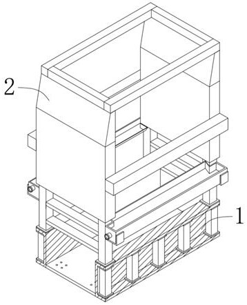
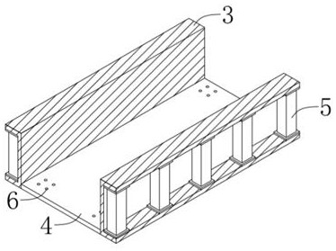
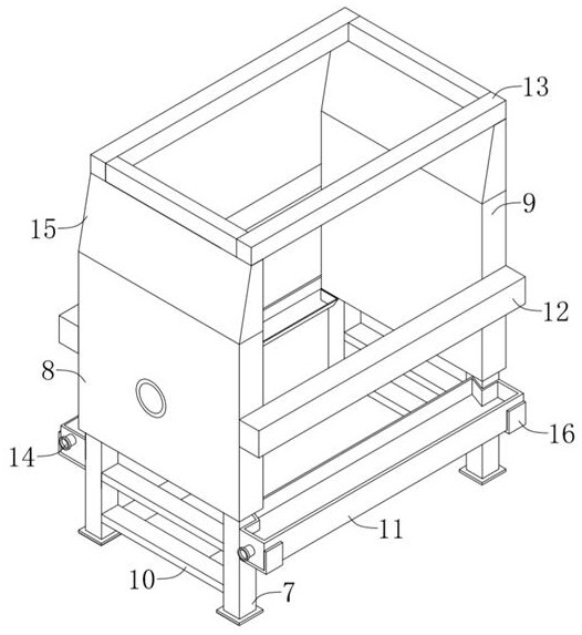
[0019] The present invention provides Figure 1-3 The machine of a filter press shown includes a machine base 1 and a frame 2. The machine base 1 includes two U-shaped support panels 3 mirrored front and rear, and a horizontal fixed connection of the two U-shaped support panels 3 The bottom plate 4 and a number of I-shaped reinforcement rods 5 arranged at equal distances across the U-shaped support panel 3 are provided on the horizontal ...


PUM


Abstract

The invention discloses a machine table of a filter press, which comprises a machine base and a rack, wherein the machine base comprises two U-shaped supporting panels arranged in a front-back mirrorimage mode, a horizontal bottom plate fixedly connected with the two U-shaped supporting panels, and a plurality of H-shaped reinforcing rods transversely arranged on the inner sides of the U-shaped supporting panels at equal intervals. The rack comprises four rectangular vertical rods fixedly arranged at the tops of the two U-shaped supporting panels; thrust plates which are fixedly arranged at the tops of the two rectangular vertical rods which are symmetrically arranged front and back on the left side; a pressing plate which is fixedly arranged at the tops of the two rectangular vertical rods which are symmetrically arranged front and back on the right side; T-shaped water receiving grooves which are formed in the outer side faces of the two rectangular vertical rods which are symmetrically arranged left and right; transverse sliding rails which are arranged on the outer side faces of the front ends and the rear ends of the thrust plate and the pressing plate; and a flushing bracketthat is arranged at the tops of the thrust plate and the pressing plate. Purified water is conveniently collected and filtered, the supporting strength is good, the stability is high, the filter plate is conveniently assisted in displacement filter pressing, and a filter plate flushing device is conveniently installed.

Description

Technical field [0001] The invention belongs to the technical field of wet slag filter press, and specifically relates to a machine platform of a filter press. Background technique [0002] Garbage incineration is an effective means of reducing, harmless, and recycling garbage, that is, through appropriate thermal decomposition, combustion, melting and other reactions, the volume of garbage is reduced by oxidation at high temperature, and it becomes residue or molten solid matter. process. After incineration, waste incineration will produce slag of 20% to 25%. The timely and stable consumption of slag has become the key to ensuring the smooth operation of waste incineration power generation projects. Slag treatment mainly uses the difference between the physical properties of the ash and slag components to carry out crushing, screening, impurity removal, magnetic separation, non-ferrous metal separation, precious metal separation, resource treatment and other links to realize i...

Claims


Application Information

Patent Timeline
Patent Type & Authority Applications(China)
IPC IPC(8): B01D25/12B01D25/30
CPCB01D25/12B01D25/30
Inventor 顾志强李海龙顾桂荣李运忠
Owner 广东忠能科技集团有限公司
Learn More