
Integrated type washing device and method for lathe dust and engine oil

A cleaning device, an integrated technology, applied in the direction of auxiliary devices, turning equipment, metal processing machinery parts, etc., can solve the problems of unguaranteed safety, time-consuming and labor-intensive cleaning, etc., and achieve convenient maintenance and disassembly , good practical effect

Active Publication Date: 2020-10-02
HEXIAN LONGSHENG PRECISION MACHINERY CO LTD
View PDF5 Cites 1 Cited by
  • Summary
  • Abstract
  • Description
  • Claims
  • Application Information

AI Technical Summary

Problems solved by technology

[0003] Therefore, when the lathe is in use, lubricating oil and engine oil are added to the lathe to ensure the normal operation of the lathe, but the oil will slowly flow to the bottom of the processing part, that is, the engine oil will be collected in the oil storage tank of the lathe. During the machining process, metal shavings will also accumulate. Metal shavings, dust and engine oil will collect together in the oil storage tank of the lathe. If it is not cleaned in time, it will cause other problems. However, the existing solution is manual cleaning. , but manual cleaning is time-consuming and laborious, and the safety cannot be guaranteed. At the same time, it is impossible to clean up metal shavings, dust and engine oil at one time

Method used


Image

  • Integrated type washing device and method for lathe dust and engine oil
  • Integrated type washing device and method for lathe dust and engine oil
  • Integrated type washing device and method for lathe dust and engine oil

Examples


Embodiment Construction

[0032] The following will clearly and completely describe the technical solutions in the embodiments of the present invention with reference to the accompanying drawings in the embodiments of the present invention. Obviously, the described embodiments are only some, not all, embodiments of the present invention. Based on the embodiments of the present invention, all other embodiments obtained by persons of ordinary skill in the art without making creative efforts belong to the protection scope of the present invention.

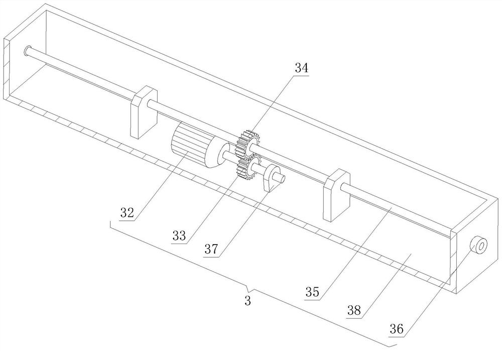
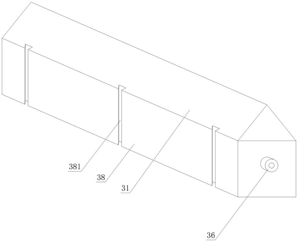
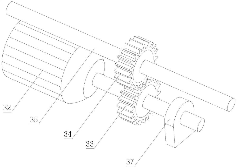
[0033] see Figure 1-7 , an integrated cleaning device for lathe dust and engine oil, including a dust collecting case 1, a frame 2 and a driving assembly 3, the driving assembly 3 serves as the power output of the entire integrated cleaning device, and the driving assembly 3 can drive the entire integrated cleaning device back and forth Move, so as to achieve the effect of cleaning the dust and oil of the lathe, the drive assembly 3 is movably connected with ...


PUM


Abstract

The invention discloses an integrated type washing device and method for lathe dust and engine oil. The integrated type washing device comprises a dust collecting shell, a frame and a drive assembly.The drive assembly is movably connected with the frame. The frame is assembled on the edge of an oil storing and dust accumulating groove of the lathe. The drive assembly comprises a triangle top base, a servo motor, a driving gear, a driven gear, a transverse shaft, a guide wheel, a bearing bush base and a framework. When the overall integrated type washing device is used, the tip end of the triangle shell extrudes metal chips, dust and engine oil into the dust collecting groove, in this way, the metal chips, the dust and the engine oil can be collected, meanwhile, leaking out of the metal chips can be avoided by means of a magnet, in this way, most metal chips and dust can be collected, however, a certain amount of engine oil stain exists, at the moment, an oil absorbing rag layer passesthrough the surface of the engine oil stain, the oil absorbing rag layer can have a function of wiping away excessive oil stain, namely, when the integrated type washing device is used, the metal chips, the dust and the engine oil can be cleared away at a time, practicality is good, and meanwhile assembling and disassembling are convenient.

Description

technical field [0001] The invention relates to a machining accessory, in particular to an integrated cleaning device and method for lathe dust and engine oil. Background technique [0002] A lathe is a machine tool that mainly uses a turning tool to turn a rotating workpiece. Drills, reamers, reamers, taps, dies and knurling tools can also be used for corresponding processing on the lathe. The lubrication method of the machine tool and the selection of lubricating grease are determined according to the structure of the machine tool, the degree of automation, the operating conditions of the machine tool and the requirements for precision. temperature rise and vibration. [0003] Therefore, when the lathe is in use, lubricating oil and engine oil are added to the lathe to ensure the normal operation of the lathe, but the oil will slowly flow to the bottom of the processing part, that is, the engine oil will be collected in the oil storage tank of the lathe. During the mach...

Claims


Application Information

Patent Timeline
IPC IPC(8): B23Q11/00B23B25/00
CPCB23B25/00B23Q11/0042B23Q11/0064
Inventor 韩年珍程华邱晨健
Owner HEXIAN LONGSHENG PRECISION MACHINERY CO LTD
Learn More