Eureka AIR delivers breakthrough ideas for toughest innovation challenges, trusted by R&D personnel around the world.

Plastic bottle recycling and separating device

A separation device and plastic bottle technology, applied in plastic recycling, recycling technology, metal processing and other directions, can solve the problems of complex device process, low separation efficiency, large workload, etc., to reduce labor intensity, rapid and convenient separation, improve The effect of work efficiency

Active Publication Date: 2020-10-02
安徽省力天新材料股份有限公司
View PDF7 Cites 3 Cited by
  • Summary
  • Abstract
  • Description
  • Claims
  • Application Information

AI Technical Summary

Problems solved by technology

[0002] With the needs of life, there are more and more plastic products, and portable drinks such as bottled mineral water are more and more popular with users because of their convenience and cleanliness, followed by a large number of plastic bottles, etc. Household garbage that is difficult to decompose. In the process of recycling plastic bottles, plastic bottles need to be separated, crushed and cleaned. Plastic bottles can be divided into bottle bodies, labels and caps, and bottle bottles according to their materials. The connection of the cover, the original separation, is to rely on manual separation, resulting in high cost and heavy workload. With the development of the times, the use of separation devices has emerged.
[0003] When the existing recovery and separation device is in use, because the plastic bottles are collected in a centralized manner during the recycling process, the shapes of the plastic bottles are different. When separating, a certain degree of screening and classification is required, and in the separation device In the process of use, the shape of the plastic bottle put into it and the direction of the inlet end need to be consistent, so that the separation work can be completed better and faster. The existing device process is relatively complicated, resulting in relatively low separation efficiency.

Method used


Image

  • Plastic bottle recycling and separating device
  • Plastic bottle recycling and separating device
  • Plastic bottle recycling and separating device

Examples


Embodiment

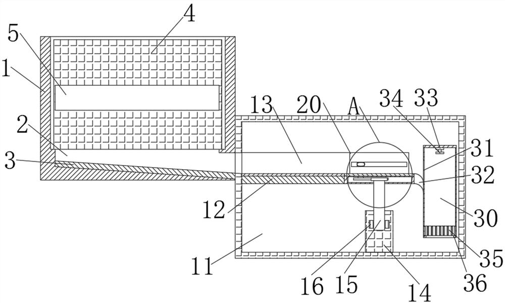
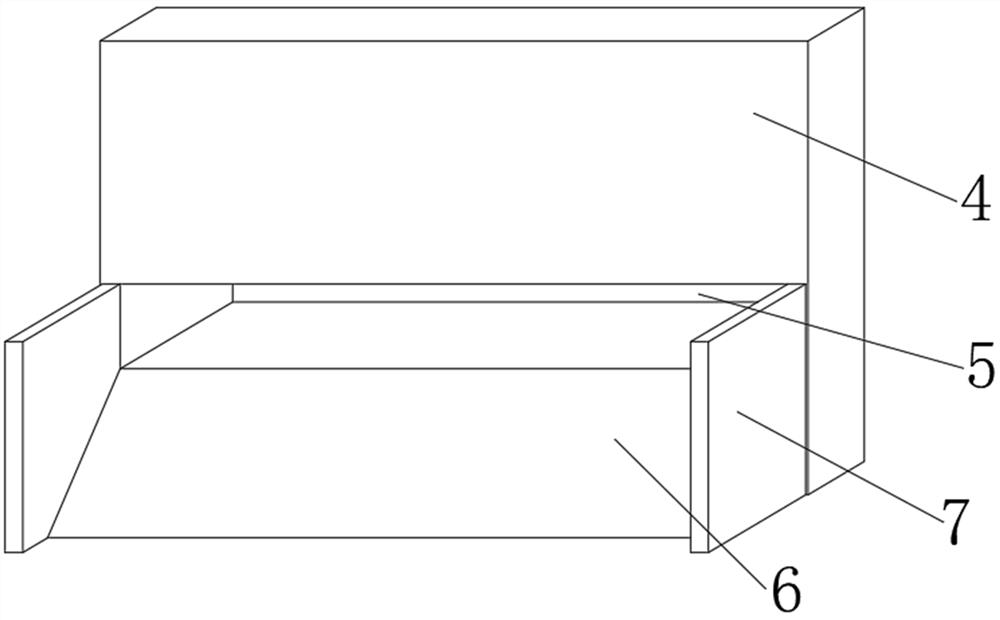
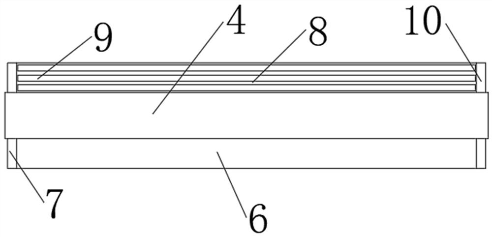
[0031] Such as Figure 1-6As shown, a plastic bottle recovery and separation device includes a sorting box (1) and a separation box (11). Several output channels (2) are opened below the interior of the sorting box (1), and the interior of the output channel (2) is provided with Conveying slide rails (3), a push plate (4) is arranged in the finishing box (1), and a through hole (5) is opened under the push plate (4), and the top of the side of the push plate (4) is connected with the finishing box (1) The inner walls are connected by telescopic rods, a separation box (11) is provided under the side of the finishing box (1), a first slope (6) is provided under the side of the push plate (4), and the first slope (6) A first side plate (7) is provided at both ends, a second slope (8) is provided under the other side of the push plate (4), and a second side plate (10) is provided at both ends of the second slope (8), Conveying rollers (9) are provided on the other side of the sec...


PUM


Abstract

The invention discloses a plastic bottle recycling and separating device. The plastic bottle recycling and separating device comprises a sorting box and a separating box, a plurality of output channels are formed in the lower portion of the interior of the sorting box, a push plate is arranged in the sorting box, a through hole is formed in the lower portion of the push plate, and the separating box is arranged below the side face of the sorting box; and a first slope is arranged below one side of the push plate, first side plates are arranged at the two ends of the first slope, a second slopeis arranged below the other side face of the push plate, and conveying rollers are arranged on the other side face of the second slope and the second slope. According to the recycling and separatingdevice, a plastic bottle transversely passes through the through hole in the push plate, automatic arrangement of the plastic bottles is achieved, and the labor intensity of workers is relieved; and arack moves, and a gear is driven to rotate, so that after a rotating disc rotates and stops rotating, the orientation of bottle openings is opposite to the orientation of the bottle openings before rotation, separation can be fast and convenient, and working efficiency is improved.

Description

technical field [0001] The invention relates to the technical field of plastic recycling equipment, in particular to a recycling and separating device for plastic bottles. Background technique [0002] With the needs of life, there are more and more plastic products, and portable drinks such as bottled mineral water are more and more popular with users because of their convenience and cleanliness, followed by a large number of plastic bottles, etc. Household garbage that is difficult to decompose. In the process of recycling plastic bottles, plastic bottles need to be separated, crushed and cleaned. Plastic bottles can be divided into bottle bodies, labels and caps, and bottle bottles according to their materials. The connection of the cover, the original separation, is to rely on manual separation, resulting in high cost and heavy workload. With the development of the times, the use of separation devices has emerged. [0003] When the existing recovery and separation devic...

Claims


Application Information

Patent Timeline
IPC IPC(8): B26D1/02B26D7/06B29B17/00
CPCB26D1/02B26D7/0608B29B17/00Y02W30/62
Inventor 李克难曹厚胜夏磊磊龚丙录
Owner 安徽省力天新材料股份有限公司
Why Eureka
Eureka Blog
Learn More