Wireless charging receiving end, wireless charging transmitting end, wireless charging system, wireless charging control method and electric vehicle

A technology of wireless charging and receiving end, which is applied in the field of transmitting end, control method, electric vehicle, system, and wireless charging receiving end, and can solve the problem of inaccurate position information obtained, inability to align power transmitting coils and power receiving coils, and interference And other issues

Active Publication Date: 2020-10-02
HUAWEI TECH CO LTD
View PDF7 Cites 7 Cited by
  • Summary
  • Abstract
  • Description
  • Claims
  • Application Information

AI Technical Summary

Problems solved by technology

However, when the adjacent parking space is also performing the alignment operation of the power transmitting coil and the power receiving coil, the low-frequency alternating magnetic field generated by the transmitting end of the adjacent parking space will interfere with the low-frequency alternating magnetic field generated by the transmitting end of the parking space. Affect the amplitude of the induction signal obtained by the receiving end of the parking space, resulting in inaccurate position information, which makes the power transmitting coil and power receiving coil unable to align

Method used


Image

  • Wireless charging receiving end, wireless charging transmitting end, wireless charging system, wireless charging control method and electric vehicle
  • Wireless charging receiving end, wireless charging transmitting end, wireless charging system, wireless charging control method and electric vehicle
  • Wireless charging receiving end, wireless charging transmitting end, wireless charging system, wireless charging control method and electric vehicle

Examples


Embodiment 1

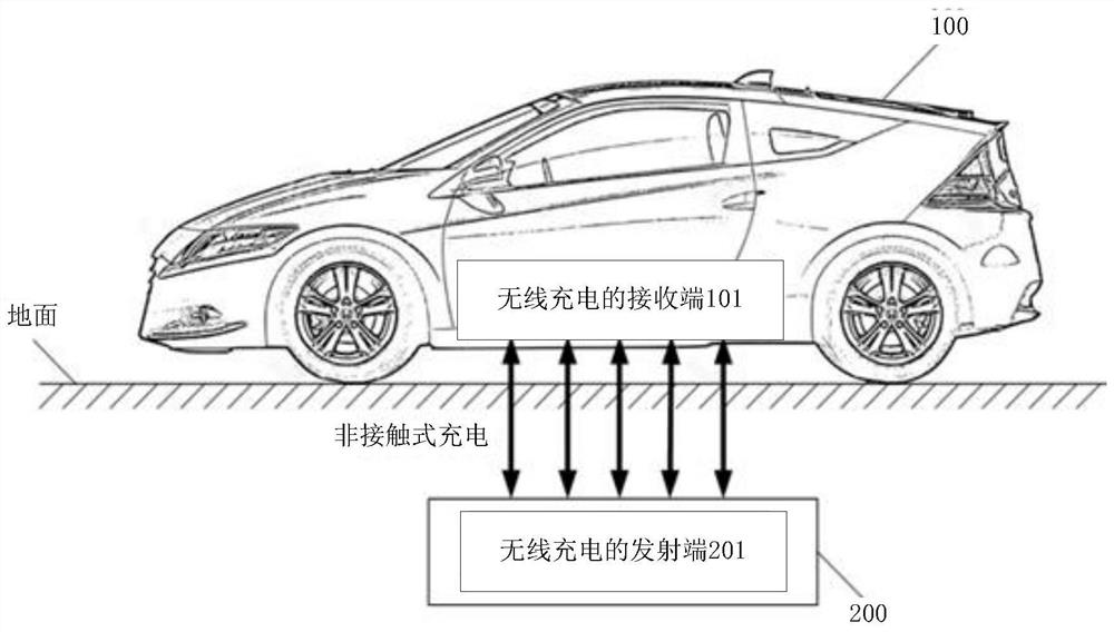
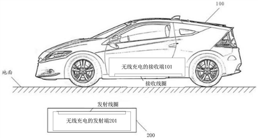
[0119] see Figure 6 , which is a schematic diagram of a wireless charging system corresponding to a wireless charging receiving end provided in an embodiment of the present application.

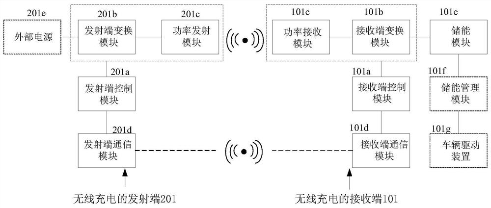
[0120] The wireless charging system includes a wireless charging receiving end 101 and a wireless charging transmitting end 201 .

[0121] Wherein, the receiving end of wireless charging (hereinafter referred to as the receiving end) 101 includes: a receiving end controller 401 , a low frequency magnetic field receiving coil 403 and a power receiving coil (not shown in the figure).

[0122] The transmitting end 201 of wireless charging (hereinafter referred to as the transmitting end) includes: a transmitting end controller 301 , a low frequency magnetic field transmitting coil 302 and a power transmitting coil (not shown in the figure).

[0123] The power transmitting coil transmits the alternating current in the form of an alternating magnetic field.

[0124] The power receiving coil con...

Embodiment 2

[0144] The working principle of the receiving end and the transmitting end when the signal characteristic is the signal pulse width is firstly described below, and the signal pulse width is the time width of the signal pulse.

[0145] see Figure 7 , which is a schematic diagram of a wireless charging system provided in an embodiment of the present application.

[0146] Wherein, the wireless charging transmitting end includes: low frequency magnetic field transmitting coils Ltx1 and Ltx2 , transmitting end controller 301 , inverter circuit 302 and low frequency magnetic field transmitting end communication module 304 .

[0147] The receiving end of wireless charging includes: low frequency magnetic field receiving coils Lrx1-Lrx4, receiving end controller 401, detection circuit 402 and low frequency magnetic field receiving end communication module 404.

[0148] In the embodiment of the present application, the inverter circuit 302 is specifically two half-bridge inverter cir...

Embodiment 3

[0179] continue to see Figure 7 , the embodiment of the present application can be implemented based on the same hardware device as the second embodiment. For the description of the hardware device, please refer to the second embodiment. , as explained below.

[0180] The signal characteristic of the embodiments of the present application is signal encoding, and the magnetic field signal emitted by the low-frequency magnetic field transmitting coil is controlled so that the magnetic field signal can represent the encoding. The following description takes binary coding as an example to explain the signal coding method used. In practical applications, other signal coding methods can also be used, such as 4-ary coding, octal coding, etc. The principles are similar, and the embodiments of this application are no longer repeat.

[0181] When the signal coding mode is binary coding, different binary numbers can be used to represent the magnetic field signal sent by a low-frequenc...


PUM


Abstract

The invention discloses a wireless charging receiving end, a wireless charging transmitting end, a wireless charging system, a wireless charging control method and an electric vehicle, whichrelate tothe technical field of wireless charging. A low-frequency magnetic field receiving coil of the receiving end converts a low-frequency magnetic field into an induction signal; when each low-frequency magnetic field transmitting coil stops working, the receiving end controller allocates a signal characteristic different from the signal characteristic of the current induction signal to each low-frequency magnetic field transmitting coil, and sends the corresponding relationship between each low-frequency magnetic field transmitting coil and the allocated signal characteristic to the wireless charging transmitting end; and the controlleris also used for determining the relative positions of the power transmitting coil and the power receiving coil by utilizing the induction signals with the distributed signal characteristics when the low-frequency magnetic field transmitting coil works. And the transmitting end controller controls the inverter circuit according to the corresponding relationso as to enable each low-frequency magnetic field transmitting coil to work. Mutual interference between low-frequency magnetic field signals of adjacent parking spaces can be avoided by utilizing the receiving end and the transmitting end.

Description

technical field [0001] The present application relates to the technical field of wireless charging, and in particular to a receiving end, a transmitting end, a system, a control method and an electric vehicle of wireless charging. Background technique [0002] With the aggravation of energy shortage and environmental pollution in modern society, electric vehicles, as new energy vehicles, have received widespread attention from all walks of life. Electric vehicles use on-board power battery packs as energy sources to drive vehicles. The charging methods of electric vehicles currently include contact charging and wireless charging, and wireless charging has become the future development of electric vehicles due to its advantages of convenient use, no sparks, no risk of electric shock, no mechanical wear, and adaptability to a variety of harsh environments and weather. direction. [0003] The wireless charging system includes a wireless charging transmitter (hereinafter refer...

Claims


Application Information

Patent Timeline
Patent Type & Authority Applications(China)
IPC IPC(8): B60L53/38H02J50/12
CPCB60L53/38H02J50/12Y02T10/70Y02T10/7072Y02T90/12Y02T90/14H02J50/80H02J50/90H02J7/00032B60L2250/16B60L53/126B60L53/36
Inventor 曾晓生游洪程毛云鹤武志贤陈双全
Owner HUAWEI TECH CO LTD
Why Eureka
Try Eureka