Eureka AIR delivers breakthrough ideas for toughest innovation challenges, trusted by R&D personnel around the world.

Cantilevered top cap transport cart system

A conveying trolley and cantilever type technology, which is applied in the field of cantilever type roof conveying trolley system, can solve the problems of complex production line structure, weak adjustment flexibility and adaptability, unfavorable cost control and production efficiency, etc.

Pending Publication Date: 2020-10-02
黄石鼎信机电有限公司
View PDF0 Cites 0 Cited by
  • Summary
  • Abstract
  • Description
  • Claims
  • Application Information

AI Technical Summary

Problems solved by technology

[0002] At present, in the automobile assembly production line, many of them use automated electrified equipment for assembly and production. This kind of production line has very high requirements for the design and precision of the equipment. Naturally, its design and operation costs are also quite high. The goals of enterprises to reduce energy consumption and improve efficiency are contradictory; at the same time, the structure of the current automated electrified production line is quite complicated, maintenance is very inconvenient, and its adjustment flexibility and adaptability are not strong. Once different workpieces need to be assembled, the production line It is necessary to make a large adjustment, which is not good for cost control and improvement of production efficiency.

Method used


Image

  • Cantilevered top cap transport cart system
  • Cantilevered top cap transport cart system
  • Cantilevered top cap transport cart system

Examples


Embodiment Construction

[0021] The technical solutions of the present invention will be clearly and completely described below in conjunction with the accompanying drawings of the present invention. Obviously, the described embodiments are only some of the embodiments of the present invention, not all of them. Based on the embodiments of the present invention, all other embodiments obtained by persons of ordinary skill in the art without making creative efforts belong to the protection scope of the present invention.

[0022] In the description of the present invention, it should be noted that the terms "upper", "lower", "inner", "outer", etc. indicate the orientation or positional relationship is based on the orientation or positional relationship shown in the drawings, or the invention The usual orientation or positional relationship when the product is used is only for the convenience of describing the present invention or simplifying the description, and does not indicate or imply that the referre...


PUM


Abstract

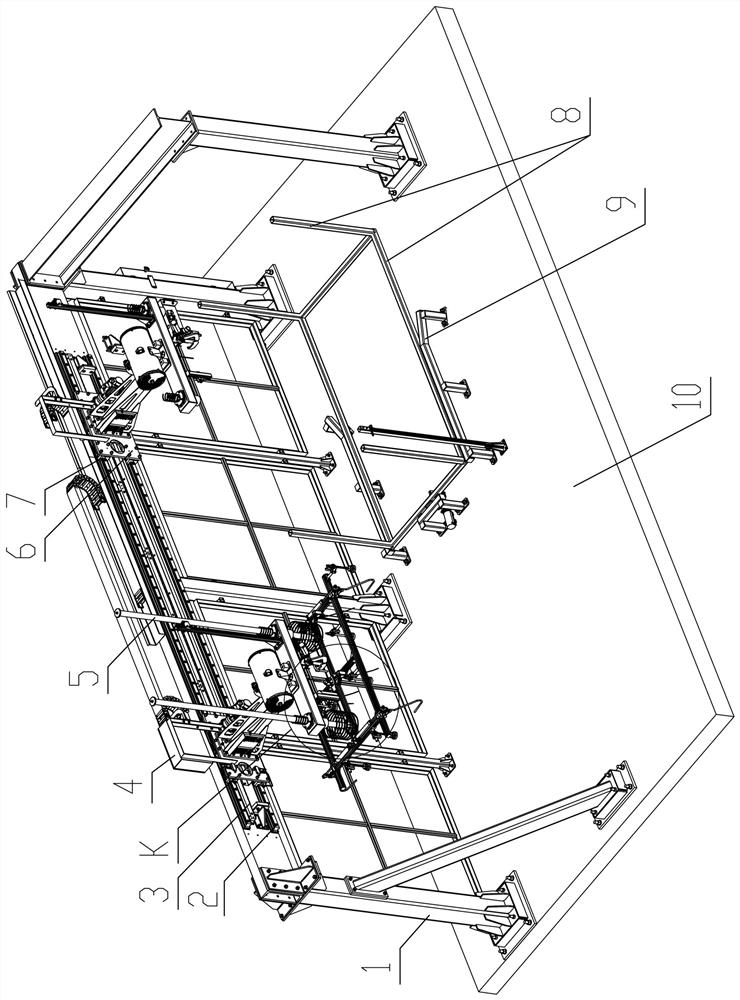
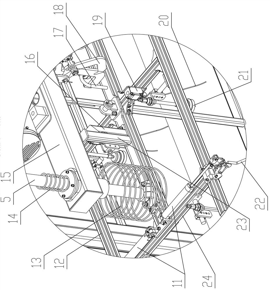
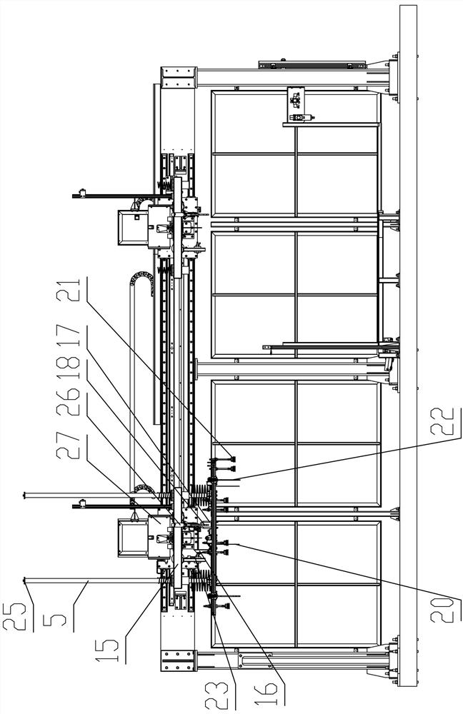
The invention relates to a cantilevered top cap transport cart system. The cantilevered top cap transport cart system comprises a support. Two sliding rails are arranged on the side wall of a cross beam in parallel in the length direction of the cross beam. A power sliding vehicle is mounted on the sliding rails. A control cabinet is mounted on the power sliding vehicle. A moving cantilever is mounted on the power sliding vehicle. A cantilever cross beam is connected to the end portion of the outer side of the moving cantilever. A pneumatic hoist is arranged at the middle of the cantilever cross beam. A cart hanging tool is arranged under the cantilever cross beam. Guiding optical shafts are arranged at the two edges of the cart hanging tool. A plurality of vacuum sucking discs are arranged at the bottom of the cart hanging tool. The bottom of the cantilever cross beam is also provided with a top position anti-falling mechanism. The bottom of the cart hanging tool is further provided with a workpiece in-place detection mechanism. The four corners of the cart hanging tool are correspondingly provided with workpiece anti-falling mechanisms. The system is novel in overall structure design, small in occupied area and open in single side, and brings more convenience to single side opening and part taking, placing and maintaining, the operation speed can be substantially increased atthe same time, and large-takt (50JPH) process using requirements are further met.

Description

technical field [0001] The invention relates to the technical field of automatic mechanical equipment, in particular to a cantilever type roof conveying trolley system. Background technique [0002] At present, in the automobile assembly production line, many of them use automated electrified equipment for assembly and production. This kind of production line has very high requirements for the design and precision of the equipment. Naturally, its design and operation costs are also quite high. The goals of enterprises to reduce energy consumption and improve efficiency are contradictory; at the same time, the structure of the current automated electrified production line is quite complicated, maintenance is very inconvenient, and its adjustment flexibility and adaptability are not strong. Once different workpieces need to be assembled, the production line It is necessary to make a large adjustment, which is not good for cost control and improvement of production efficiency. ...

Claims


Application Information

Patent Timeline
IPC IPC(8): B66C11/04B66C13/20B66C1/34B66C15/00B66C9/14B66C13/08
CPCB66C1/34B66C9/14B66C11/04B66C13/08B66C13/20B66C15/00
Inventor 张泉胜
Owner 黄石鼎信机电有限公司
Why Eureka
Eureka Blog
Learn More