Sealing structure for preventing air leakage of tuyere sleeve joint surface and tuyere sleeve structure

A technology of sealing structure and tuyere cover, applied in the direction of engine seal, tuyere, pipe/pipe joint/pipe fitting, etc., can solve the problems of gas leakage, leakage, difficulty in maintenance and replacement, etc., and achieve the effect of improving the working environment

Pending Publication Date: 2020-10-02
MCC CAPITAL ENGINEERING & RESEARCH
View PDF0 Cites 2 Cited by
  • Summary
  • Abstract
  • Description
  • Claims
  • Application Information

AI Technical Summary

Problems solved by technology

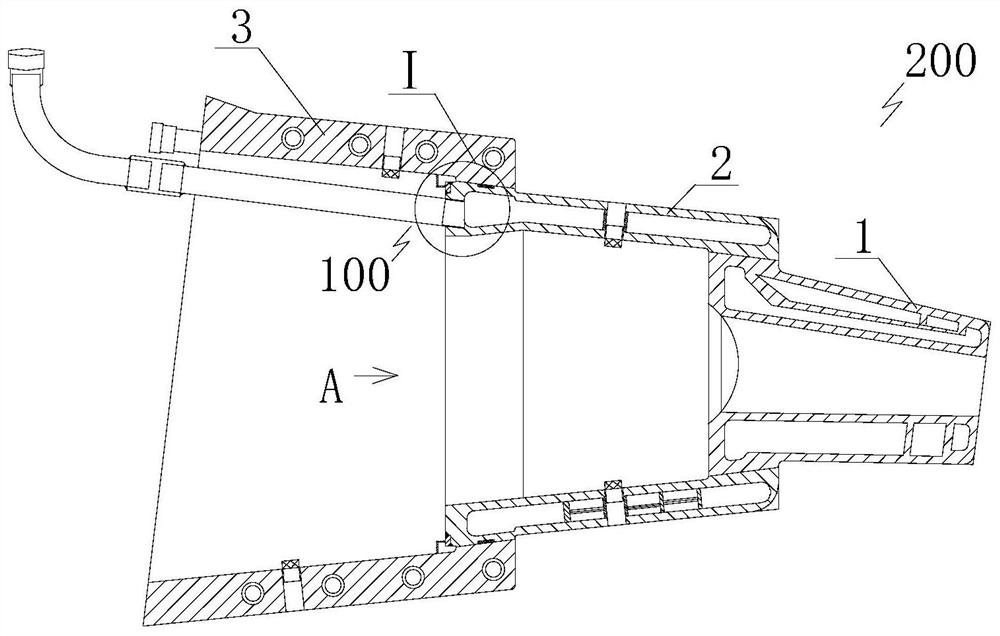
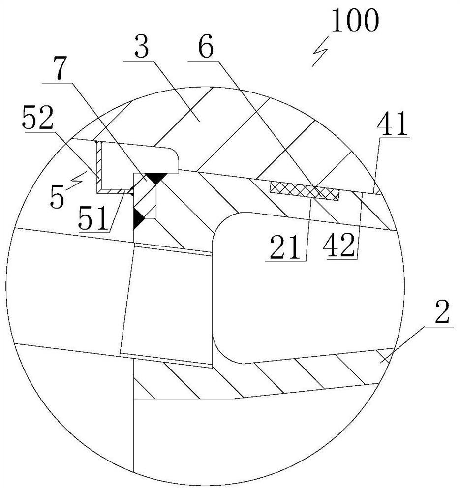
[0005] The object of the present invention is to provide a sealing structure and a tuyere cover structure that prevents air leakage from the joint surface of the tuyere cover, and overcomes the problems in the prior art that the cover in the tuyere is easily deformed to cause leakage and difficult maintenance and replacement. The triple sealing function can effectively solve the problem of gas leakage caused by the gap between the joint surface of the tuyere middle sleeve and the tuyere large sleeve after the tuyere middle sleeve is upturned and deformed, and can effectively improve the working environment in the tuyere area. effective measures

Method used


Image

  • Sealing structure for preventing air leakage of tuyere sleeve joint surface and tuyere sleeve structure
  • Sealing structure for preventing air leakage of tuyere sleeve joint surface and tuyere sleeve structure
  • Sealing structure for preventing air leakage of tuyere sleeve joint surface and tuyere sleeve structure

Examples


Embodiment Construction

[0036] In order to have a clearer understanding of the technical features, purposes and effects of the present invention, the specific implementation manners of the present invention will now be described with reference to the accompanying drawings.

[0037] The specific implementations of the present invention described here are only for the purpose of explaining the present invention, and should not be construed as limiting the present invention in any way. Under the teaching of the present invention, the skilled person can conceive any possible modification based on the present invention, and these should be regarded as belonging to the scope of the present invention. It should be noted that when an element is referred to as being “disposed on” another element, it may be directly on the other element or there may also be an intervening element. When an element is referred to as being "connected to" another element, it can be directly connected to the other element or interv...


PUM


Abstract

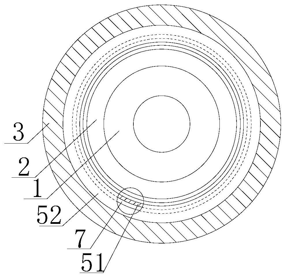
The invention relates to a sealing structure for preventing air leakage of a tuyere sleeve joint surface and a tuyere sleeve structure. The sealing structure comprises an inner conical surface arranged on the inner wall of the small-diameter end of a tuyere large sleeve and an outer conical surface arranged on the outer wall of the large-diameter end of a tuyere middle sleeve, the outer conical surface can abut against the inner conical surface in a sealed mode, and a sealing ring is arranged between the outer conical surface and the inner conical surface; the sealing structure for preventingair leakage of the tuyere sleeve joint surface further comprises a sealing ring plate capable of absorbing deformation of the tuyere middle sleeve, the radial inner side of the sealing ring plate canbe fixedly connected with the end face of the large-diameter end of the tuyere middle sleeve in a sealed mode, and the radial outer side of the sealing ring plate can be connected with the inner sideface of the tuyere large sleeve in a sealed abutting mode. According to the sealing structure for preventing air leakage of the tuyere sleeve joint surface, the sealing structure can play a triple sealing role, can effectively solve the problem of gas leakage caused by a gap generated between the joint surfaces of the tuyere middle sleeve and the tuyere large sleeve after the tuyere middle sleeveis upwarped and deformed, effectively improves the working environment of a tuyere area, and is an effective measure for realizing the safety production of a blast furnace.

Description

technical field [0001] The invention relates to the technical field of iron and steel metallurgy, in particular to a sealing structure and a tuyere cover structure for preventing air leakage from a joint surface of a tuyere cover. Background technique [0002] During the blast furnace smelting process, complex physical and chemical reactions will take place in the furnace, and some harmful elements such as alkali metals and zinc will be brought into the furnace charge. Circular enrichment, especially in the tuyere area, a large amount of alkali metal and zinc will be found when the tuyere is replaced. In addition, alkali metal and zinc will penetrate into the refractory material, causing abnormal expansion of the refractory material. The corrosion mechanism is as follows: Alkali metals (K, Na) are easy to form low melting point substances in the blast furnace, and chemically react with the refractory material, causing the strength of the refractory material to decrease and a...

Claims


Application Information

Patent Timeline
Patent Type & Authority Applications(China)
IPC IPC(8): F16J15/06F16J15/04F16L25/14C21B7/16
CPCC21B7/16F16J15/04F16J15/06F16J15/061F16J15/064F16L25/14
Inventor 王春龙赵艳霞全强段国建祁四清陈秀娟曹英杰
Owner MCC CAPITAL ENGINEERING & RESEARCH
Why Eureka
Try Eureka