A quick-drying drip rack
A drip rack and dry technology, applied in the field of drip racks, can solve the problems of low energy consumption, low drying efficiency, lower device use costs, etc., and achieve the effects of low energy consumption, lower energy costs, and reduced thickness
- Summary
- Abstract
- Description
- Claims
- Application Information
AI Technical Summary
Problems solved by technology
Method used
Image

Examples
Embodiment
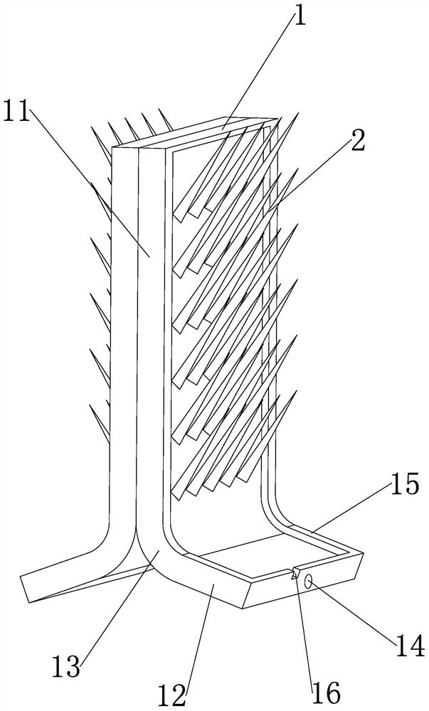
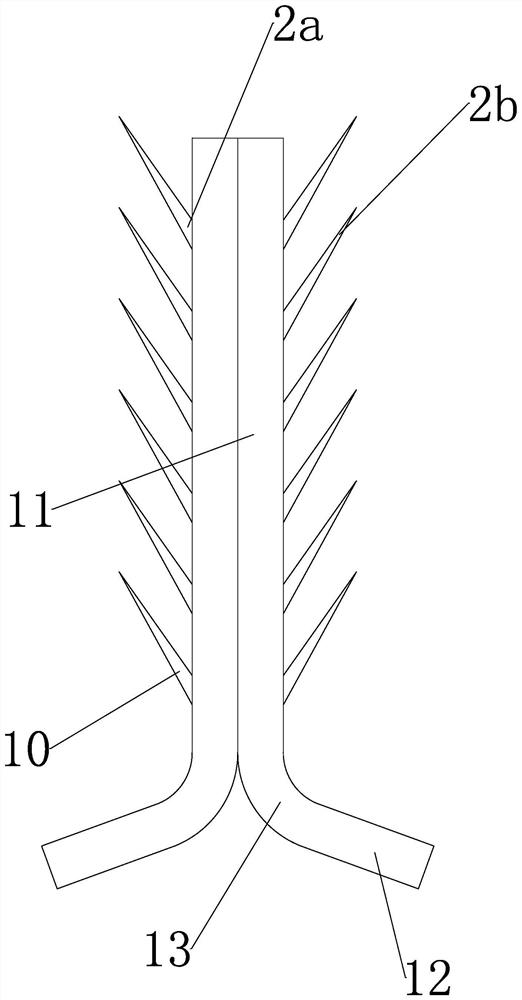
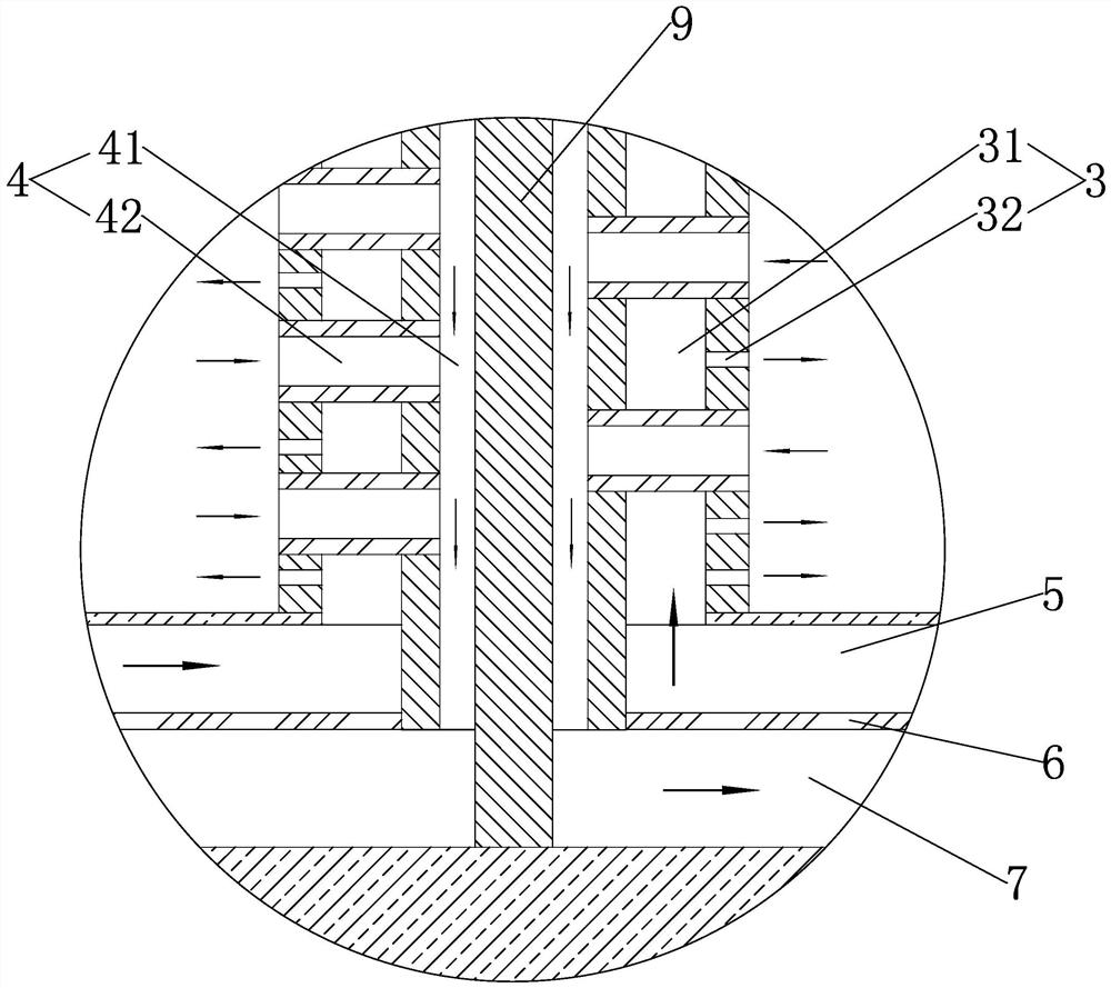
[0028] Such as Figure 1 to Figure 4 As shown, a quick-drying drip rack includes a body 1 and a drip stick group arranged on the side of the body. The drip stick group includes several drip sticks 2 arranged at intervals, and a drying flow is arranged inside the drip stick along its length direction. 3 and condensing channel 4, inside the main body along its thickness direction are provided with a drying layer 5, heat insulation layer 6 and condensation layer 7 in sequence, a heating element 8 is arranged in the hollow drying layer, and the drying layer and the peripheral The fan is connected, and the hollow condensation layer is connected with the peripheral vacuum pump. The air injected by the fan into the drying layer is heated by the heating element and then flows into the container along the drying channel. The mixed gas of water vapor and air flows out of the container under the action of the vacuum pump. Flow into the condensate layer along the condensate flow path; the...
PUM
 Abstract
Description
Claims
Application Information
 - R&D
- Intellectual Property
- Life Sciences
- Materials
- Tech Scout
- Unparalleled Data Quality
- Higher Quality Content
- 60% Fewer Hallucinations
Browse by: Latest US Patents, China's latest patents, Technical Efficacy Thesaurus, Application Domain, Technology Topic, Popular Technical Reports.
© 2025 PatSnap. All rights reserved.Legal|Privacy policy|Modern Slavery Act Transparency Statement|Sitemap|About US| Contact US: help@patsnap.com