Petrochemical waste heat recovery device

A waste heat recovery device and petrochemical technology, which is applied in the field of chemical manufacturing to achieve the effects of high degree of automation, safe use and accelerated adsorption

Active Publication Date: 2020-10-02
德州星宇换热器机械制造有限公司
View PDF7 Cites 2 Cited by
  • Summary
  • Abstract
  • Description
  • Claims
  • Application Information

AI Technical Summary

Problems solved by technology

However, the equipment improves the waste heat a

Method used


Image

  • Petrochemical waste heat recovery device
  • Petrochemical waste heat recovery device
  • Petrochemical waste heat recovery device

Examples


specific Embodiment approach 1

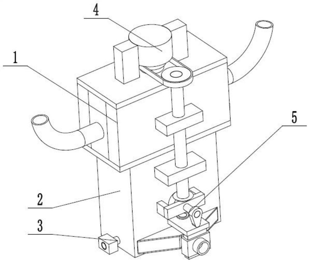
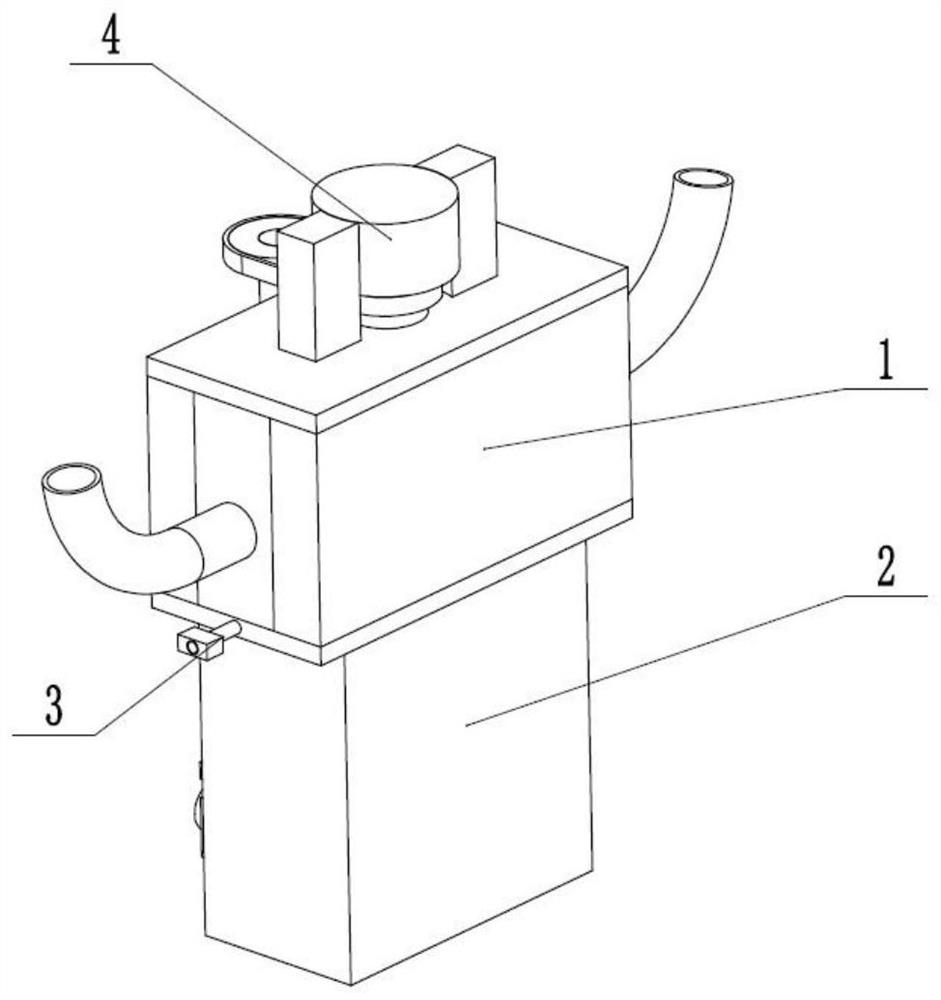
[0029] like Figure 1 to Figure 9 As shown, a petrochemical waste heat recovery device includes a waste heat recovery frame 1, a sealed waste heat absorption frame 2, a heat recovery device 3, a stable pressurized heat absorber 4 and a linkage pressure bearing valve 5. The waste heat recovery frame 1 It is fixedly connected and communicated with the upper end of the sealed waste heat absorption frame 2, the heat recovery device 3 is fixedly connected in the sealed waste heat absorption frame 2, and the stable pressurized heat absorber 4 is rotatably connected in the waste heat recovery frame 1 to stably pressurize and absorb heat The device 4 is linked with the pressure-bearing valve 5 through the meshing transmission connection. By continuously adding hot air with waste heat into the waste heat recovery frame 1, the hot air flows through the sealed waste heat absorption frame 2 and the heat recovery device 3, and the heat recovery device 3 absorbs heat and is discharged. Und...

specific Embodiment approach 2

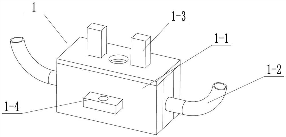
[0031] like Figure 1 to Figure 9As shown, this embodiment further explains Embodiment 1. The waste heat recovery frame 1 includes a recovery frame 1-1, two waste heat addition pipes 1-2, a motor fixing seat 1-3, a fixed rotating seat 1-4, Two spacers 1-5, two sliding extrusion slots 1-6, two side chute 1-7, four fixed sliding shafts 1-8 and four springs 1-9, recovery frame 1-1 The two ends are respectively fixedly connected and communicated with two waste heat adding pipes 1-2, the motor fixing base 1-3 is fixedly connected to the upper end of the recovery frame 1-1, and the fixed rotating base 1-4 is fixedly connected to the rear end of the recovery frame 1-1 , the two spacers 1-5 are fixedly connected to the inner wall of the recovery frame 1-1, the two spacers 1-5 are provided with sliding extrusion slots 1-6, and the two side slide grooves 1-7 are respectively provided At both ends of the recovery frame 1-1, two side chutes 1-7 are respectively connected to two waste hea...

specific Embodiment approach 3

[0033] like Figure 1 to Figure 9 As shown, this embodiment further describes Embodiment 2. The sealed waste heat absorption frame 2 includes a sealed pressure-bearing frame 2-1, a fixed frame 2-2, a conical collection and discharge frame 2-3, and a discharge pipe 2. -4 and the fixed sealing sliding frame 2-5, the sealing pressure bearing frame 2-1 is fixedly connected to the lower end of the recovery frame 1-1, the fixed frame 2-2 is fixedly connected to the rear end of the sealing pressure bearing frame 2-1, tapered The collection and discharge frame 2-3 is fixedly connected and communicated with the lower side of the rear end of the sealed pressure-bearing frame 2-1, the discharge pipe 2-4 is fixedly connected and communicated with the conical collection and discharge frame 2-3, and the discharge pipe 2-4 is fixedly connected And communicate with fixed sealing sliding frame 2-5. The gas is easily collected in the conical collection and discharge frame 2-3 and discharged th...


PUM


Abstract

The invention relates to the field of chemical manufacturing, in particular to a petrochemical waste heat recovery device comprising a waste heat recovery frame, a sealed waste heat absorption frame,a heat recovery device, a stable pressurizing heat absorber and a linkage pressure-bearing valve. The waste heat recovery frame is fixedly connected and communicates with the upper end of the sealed waste heat absorption frame; the heat recovery device is fixedly connected into the sealed waste heat absorption frame; the stable pressurizing heat absorber is rotatably connected into the waste heatrecovery frame; and the stable pressurizing heat absorber is in transmission connection with the linkage pressure-bearing valve in a meshed manner. The petrochemical waste heat recovery device has theadvantages that the pressure of the waste heat adsorption environment is increased, the heat adsorption is accelerated, and the heat loss of the waste heat is further reduced; the waste heat adsorption environment is continuously changed through continuously circulating modes of continuous pressurization, pressure discharge, air intake and re-pressurization, continuous increase of the pressure ofthe waste heat adsorption environment is realized, and continuous heat absorption is realized; and the automation degree is high, the operation is convenient, and the use is safe.

Description

technical field [0001] The invention relates to the field of chemical manufacturing, in particular to a petrochemical waste heat recovery device. Background technique [0002] The patent number is CN201810708390.6, which discloses a waste heat recovery device for industrial waste gas treatment, including a bidirectional drive device, a first waste heat recovery device box, an air guiding device, a second waste heat recovery device box, a low-temperature outlet pipe, and two swing heat absorbers The device, the exhaust gas inlet pipe and two waste heat recovery pipes are characterized in that: the left and right ends of the two-way drive device are respectively slidably connected to the first waste heat recovery device box and the second waste heat recovery device box, and the air guiding device communicates with The first waste heat recovery device box and the second waste heat recovery device box, the low-temperature air outlet pipe is connected to the second waste heat rec...

Claims


Application Information

Patent Timeline
IPC IPC(8): F28D21/00F28F9/00
CPCF28D21/0014F28F9/00Y02P20/10
Inventor 于伟
Owner 德州星宇换热器机械制造有限公司
Why Eureka
Try Eureka