AR glasses and synchronous folding structure of optical-mechanical glasses legs of AR glasses

A folding structure and mirror leg technology, applied in the field of AR, can solve problems such as breakage, unsuitable for carrying, and large space occupation

Active Publication Date: 2020-10-02
GEER TECH CO LTD
View PDF8 Cites 6 Cited by
  • Summary
  • Abstract
  • Description
  • Claims
  • Application Information

AI Technical Summary

Problems solved by technology

AR glasses are mainly composed of optics, temples, lenses, and frames. The optics and optical components are generally installed on the frame, which causes the optics to occupy most of the space on the side of the temples, and generally the temples cannot be folded. , not suitable for carrying, it takes up a lot of space
[0005] In addition, for some products whose temples can be folded, since the optical machine is arranged on the side of the frame, hardware such as a power supply board needs to be installed on the temple side, and the power supply board and other hardware are connected to the optical machine through multiple signal lines or power supply lines, and Each cable needs to pass through the rotating shaft. When the mirror legs are folded and unfolded repeatedly, the internal cables will move accordingly, which will easily cause the cables to loosen and break. The connection reliability of the cables is difficult to guarantee, and the service life is relatively long. short

Method used


Image

  • AR glasses and synchronous folding structure of optical-mechanical glasses legs of AR glasses
  • AR glasses and synchronous folding structure of optical-mechanical glasses legs of AR glasses
  • AR glasses and synchronous folding structure of optical-mechanical glasses legs of AR glasses

Examples


Embodiment Construction

[0052] The following will clearly and completely describe the technical solutions in the embodiments of the present invention with reference to the accompanying drawings in the embodiments of the present invention. Obviously, the described embodiments are only some, not all, embodiments of the present invention. Based on the embodiments of the present invention, all other embodiments obtained by persons of ordinary skill in the art without making creative efforts belong to the protection scope of the present invention.

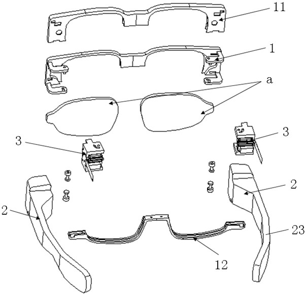
[0053] Please refer to figure 1 , figure 1 It is a schematic diagram of the overall structure of a specific embodiment provided by the present invention.

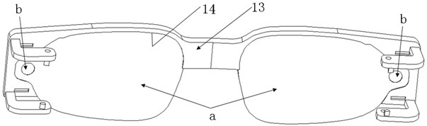
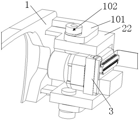
[0054] In a specific embodiment provided by the present invention, the optical-mechanical temple synchronous folding structure mainly includes a mounting bracket 1 , a temple assembly 2 and an optical-mechanical assembly 3 .

[0055] Wherein, the mounting bracket 1 is mainly used for mounting the optical ...


PUM


Abstract

The invention discloses a synchronous folding structure for optical-mechanical glasses legs. The synchronous folding structure comprises an installation support which is used for installing optical waveguide lens, glasses leg assemblies which are connected to the two sides of the installation support in a turnover mode, and optical machine assemblies which are installed in the glasses leg assemblies in an integrated mode, and the light-emitting direction of the optical machine assemblies is aligned with an incident area of the optical waveguide lens when the optical machine assemblies are turned over to be in an unfolded state along with the glasses leg assemblies. Therefore, the folding or unfolding state switching of the glasses leg assemblies can be realized through the folding movementof the glasses leg assemblies on the installation support, and the storage and the carrying are conveniently realized; meanwhile, the optical machine assemblies integrally mounted in the glasses legassemblies; when the glasses leg assemblies are turned over, the optical machine assemblies and the glasses leg assemblies are kept static relatively, so that an internal cable does not move relatively, the internal cable can be prevented from loosening or breaking due to relative movement on the basis of realizing a glasses leg folding function, and the cable connection reliability is improved. The invention further discloses AR glasses, and the beneficial effects of the AR glasses are as described above.

Description

technical field [0001] The invention relates to the field of AR technology, in particular to an optical-mechanical mirror leg synchronous folding structure. The present invention also relates to AR glasses. Background technique [0002] With the development of AR technology, more and more AR devices have been widely used. [0003] AR (Augmented Reality, Augmented Reality) technology is a technology that ingeniously integrates virtual information with the real world. It uses multimedia, 3D modeling, real-time tracking and registration, intelligent interaction, sensing and other technical means to integrate computer The generated text, images, 3D models, music, video and other virtual information are simulated and applied to the real world, and the two kinds of information complement each other, thereby realizing the "enhancement" of the real world. [0004] At present, AR products are getting lighter and lighter, and AR products in the form of glasses are becoming more and ...

Claims


Application Information

Patent Timeline
Patent Type & Authority Applications(China)
IPC IPC(8): G02B27/01
CPCG02B27/0176G02B2027/0178
Inventor 李传龙姜滨迟小羽
Owner GEER TECH CO LTD
Why Eureka
Try Eureka