
LED dimming drive circuit, dimming method and dimming system

A technology of dimming drive and LED lights, which is applied in the direction of electrical components, energy-saving control technology, etc., and can solve the problems of over-adjustment of brightness and increase the experience of dimming

Pending Publication Date: 2020-10-02
HANGZHOU SILAN MICROELECTRONICS
View PDF0 Cites 2 Cited by
  • Summary
  • Abstract
  • Description
  • Claims
  • Application Information

AI Technical Summary

Problems solved by technology

[0005] The purpose of the present invention is to provide an LED dimming drive circuit, a dimming method and a dimming system to solve the problem of over-adjustment of the brightness caused by the delay of the shutdown action, and to increase the user's dimming experience

Method used


Image

  • LED dimming drive circuit, dimming method and dimming system
  • LED dimming drive circuit, dimming method and dimming system
  • LED dimming drive circuit, dimming method and dimming system

Examples


Embodiment Construction

[0110] The LED dimming driving circuit, dimming method and dimming system proposed by the present invention will be further described in detail below in conjunction with the accompanying drawings and specific embodiments. The advantages and features of the present invention will be more clearly understood from the following examples. It should be noted that all the drawings are in a very simplified form and use imprecise scales, and are only used to facilitate and clearly assist the purpose of illustrating the embodiments of the present invention.

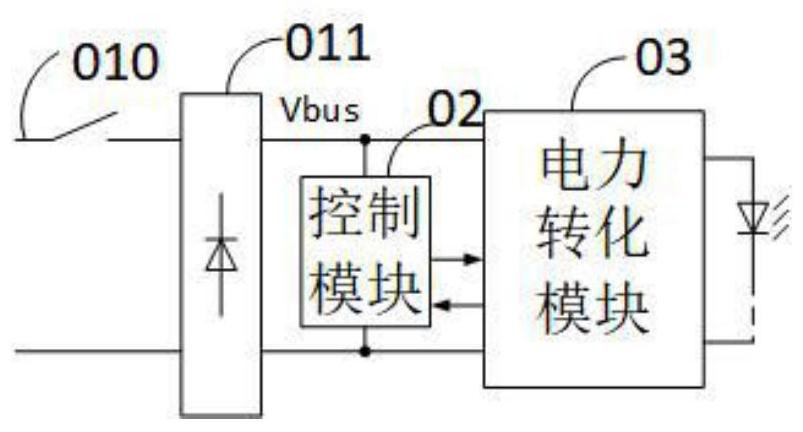
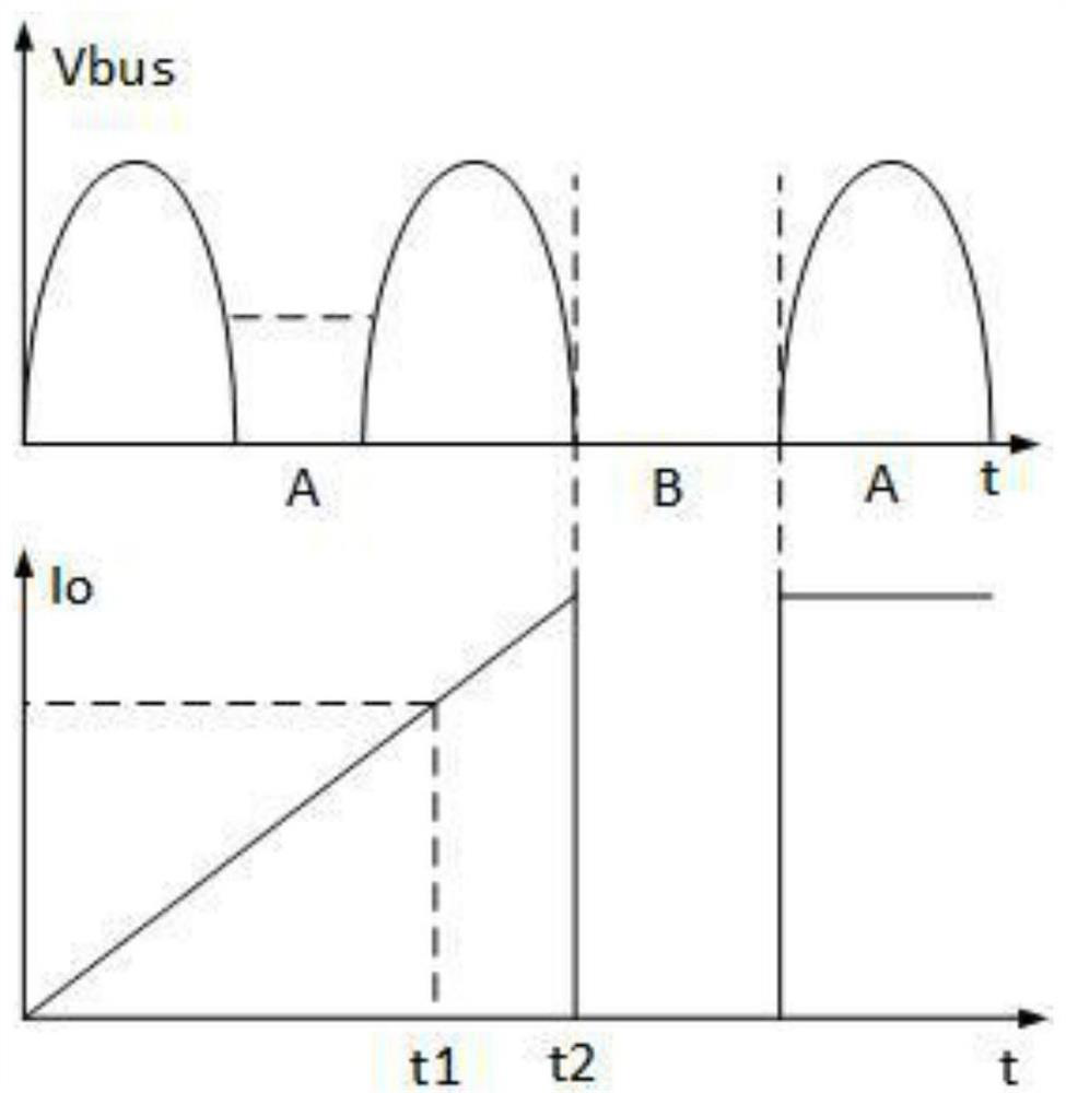
[0111] refer to figure 1 , shows a schematic block diagram of a dimming system in the prior art. The block diagram includes a power switch 010 , a rectifier bridge 011 , a control module 02 and a power conversion module 03 . The input of the AC voltage can be controlled by turning on and off the power switch 010 , and the rectifier bridge 011 is used to rectify the AC input voltage to obtain the DC bus voltage Vbus. The control ...


PUM


Abstract

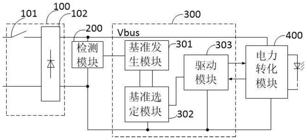
The invention provides an LED dimming drive circuit, a dimming method and a dimming system. The LED dimming drive circuit comprises a reference generation module, a reference selection module and a drive module. The dimming reference signal and the reference compensation holding signal can be generated simultaneously through the reference generation module, and the difference between the actual reference signal and the expected reference signal caused by shutdown delay is compensated through the reference compensation holding signal, so that the problem of over-dimming of brightness caused byshutdown action delay can be solved, and the dimming experience of a user is improved.

Description

technical field [0001] The invention relates to the technical field of power electronics, in particular to an LED dimming drive circuit, a dimming method and a dimming system. Background technique [0002] As people's requirements for energy saving are getting higher and higher, lights with dimming function appear. The light can change the brightness and color of the light to achieve a certain degree of comfort and meet people's requirements for energy saving. The types of lights with dimming function include bulb lights, down lights, T-tube lights, panel lights and the like. [0003] However, general households and companies control the on and off of lights through wall power switches, and do not reserve dimmers on the walls, so they can only be dimmed by switches. The existing dimming method is to realize dimming through the control module to detect the on-off of the power switch, but there will be a shutdown delay, so that the brightness at the next turn-on is not the b...

Claims


Application Information

Patent Timeline
Patent Type & Authority Applications(China)
IPC IPC(8): H05B45/325H05B45/10
CPCH05B45/325H05B45/10Y02B20/40
Inventor 叶美盼
Owner HANGZHOU SILAN MICROELECTRONICS
Learn More