Check patentability & draft patents in minutes with Patsnap Eureka AI!

Manufacturing method of microfluidic actuator module

A manufacturing method and actuator technology, applied in the direction of electric solid devices, semiconductor devices, fluid velocity measurement, etc.

Active Publication Date: 2020-10-09
MICROJET TECH
View PDF6 Cites 0 Cited by
  • Summary
  • Abstract
  • Description
  • Claims
  • Application Information

AI Technical Summary

Problems solved by technology

The outlet openings respectively communicate with the nozzles through the fluid outlets

Method used


Image

  • Manufacturing method of microfluidic actuator module
  • Manufacturing method of microfluidic actuator module
  • Manufacturing method of microfluidic actuator module

Examples


Embodiment Construction

[0069] Embodiments embodying the features and advantages of this case will be described in detail in the description of the latter paragraph. It should be understood that the present case can have various changes in different aspects without departing from the scope of the present case, and the descriptions and diagrams therein are used for illustration in nature rather than limiting the present case.

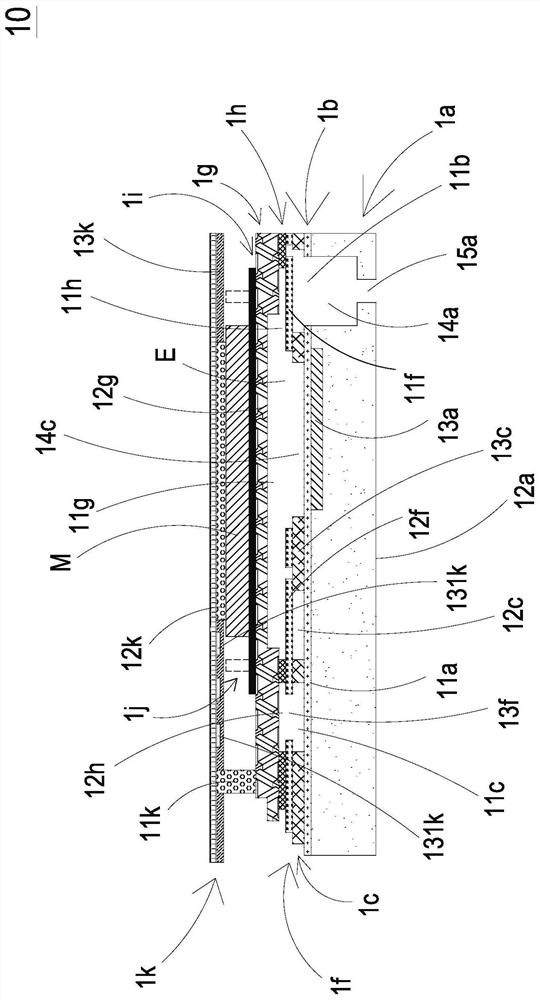
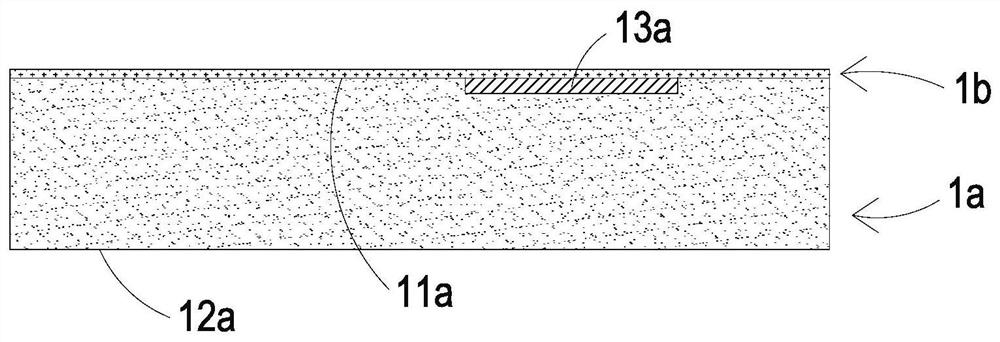
[0070] The microfluidic actuators in this case are used to transport fluids, see figure 1 as well as Figure 4 , in the embodiment of this case, the microfluidic actuator module 100 includes a plurality of microfluidic actuators 10, and consists of a first substrate 1a, a first protective layer 1b, a first photoresist layer 1c, an auxiliary substrate 1d (as shown in Figure 2H to Figure 2J), a film adhesive layer 1e (as shown in Figure 2H to Figure 2J), a valve layer 1f, a second substrate 1g, a second photoresist layer 1h, and a conductive adhesive layer 1i, a piezoelectric l...


PUM


Abstract

The invention discloses a manufacturing method of a microfluidic actuator module. The manufacturing method comprises the following steps: step 1, providing a first substrate, depositing and etching afirst protective layer; step 2, rolling and developing a first photoresist layer on the first protective layer; step 3, providing an auxiliary substrate to roll and etch a thin film adhesive layer anda valve layer; step 4, overturning, aligning and jointing the valve layer on the first photoresist layer; step 5, providing a second substrate; step 6, rolling and developing the second substrate onthe second photoresist layer; step 7, bonding the second photoresist layer to the valve layer in a flip-chip and hot-pressing mode; step 8, performing screen printing of a conductive adhesive layer onthe second substrate; step 9, adhering a piezoelectric layer to the conductive adhesive layer; and step 10, welding an electrode layer to the piezoelectric layer and the second substrate .

Description

technical field [0001] This case relates to a method for manufacturing a microfluidic actuator module, especially a method for manufacturing a microfluidic actuator module using micro-electromechanical surface and body processing. Background technique [0002] At present, in various fields, whether it is medicine, computer technology, printing, energy and other industries, products are developing towards refinement and miniaturization. Among them, the fluid contained in products such as micro pumps, sprayers, inkjet heads, and industrial printing devices The actuator is its key technology. [0003] With the rapid development of science and technology, the application of fluid conveying structure is becoming more and more diversified, such as industrial application, biomedical application, medical care, electronic heat dissipation, etc., and even the recent popular wearable devices can be seen. It can be seen that traditional fluid actuators are gradually trending toward dev...

Claims


Application Information

Patent Timeline
IPC IPC(8): B81C1/00B81B7/00
CPCB81C1/00119B81C1/00015B81B7/00B81B2201/03
Inventor 莫皓然余荣侯张正明戴贤忠廖文雄黄启峰韩永隆陈宣恺
Owner MICROJET TECH
Features
  • R&D
  • Intellectual Property
  • Life Sciences
  • Materials
  • Tech Scout
  • Unparalleled Data Quality
  • Higher Quality Content
  • 60% Fewer Hallucinations
Learn More