Highway bridge pile foundation drilling device and using method thereof

A technology for drilling devices and highway bridges, which is applied in the direction of drilling equipment and methods, electromechanical devices, supporting devices, etc., which can solve problems such as falling into cavities, scattering, and affecting the effect of concrete pouring, and achieve the effect of improving stability

Inactive Publication Date: 2020-10-09
京山俊平机电科技有限公司
View PDF8 Cites 0 Cited by
  • Summary
  • Abstract
  • Description
  • Claims
  • Application Information

AI Technical Summary

Problems solved by technology

[0003] Most of the current pile foundation drilling devices are directly installed on the corresponding mechanical arms. Although it is possible to drill holes on ground with different slopes, during the drilling process, only relying on the mechanical arm for support cannot guarantee that the drilling device The stability during the drilling process cannot further improve the stability of the drilling device to ensure that the holes in the pile foundation can meet the expected standards; currently, when constructing cast-in-situ piles, it is usually necessary to drill holes at the corresponding positions on the ground first. , During the drilling process, the discharged soil is often concentrated near the hole. If the soil quality is relatively loose, the soil next to the hole is easy to fall into the hole again, causing the depth of the hole to fall into the soil, and it is easy to affect the follow-up The effect of concrete pouring; and the current drilling device is often removed directly from the hole after drilling. If the soil in this area is relatively loose, the soil on the inner wall of the hole will easily collapse after the drill bit is removed and fall into the cavity. It affects the actual use effect of the hole, and it is impossible to tighten the inner wall of the hole in time after the hole is drilled to ensure that the inner wall of the hole is more stable; at the same time, after the current drilling device is continuously drilling, most of its drive motor Heat dissipation dissipates heat to the external environment, and it is impossible to improve the heat dissipation effect of the drive motor and at the same time discharge the dust generated by drilling in a directional manner, so as to avoid dust flying around the drilling device and affect the operator's observation of the drilling place

Method used


Image

  • Highway bridge pile foundation drilling device and using method thereof
  • Highway bridge pile foundation drilling device and using method thereof
  • Highway bridge pile foundation drilling device and using method thereof

Examples


Embodiment 1

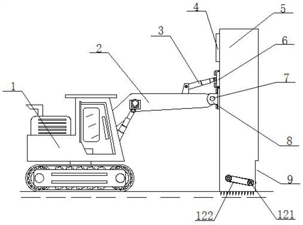
[0041] Example 1, such as figure 1 As shown, before drilling, the main body of the excavator 1 controls the opening of the mechanical arm 2 to a suitable angle, and then controls the extension of the telescopic hydraulic cylinder A3 to control the angle between the main body compartment 5 and the ground, and then controls the mechanical arm 2 Lower a little until the bottom of the main body compartment 5 is close to the ground, so that the main body compartment 5 is fixed on the ground at an appropriate angle, and then the ground is drilled through the drilling holes inside the main body compartment 5 .

Embodiment 2

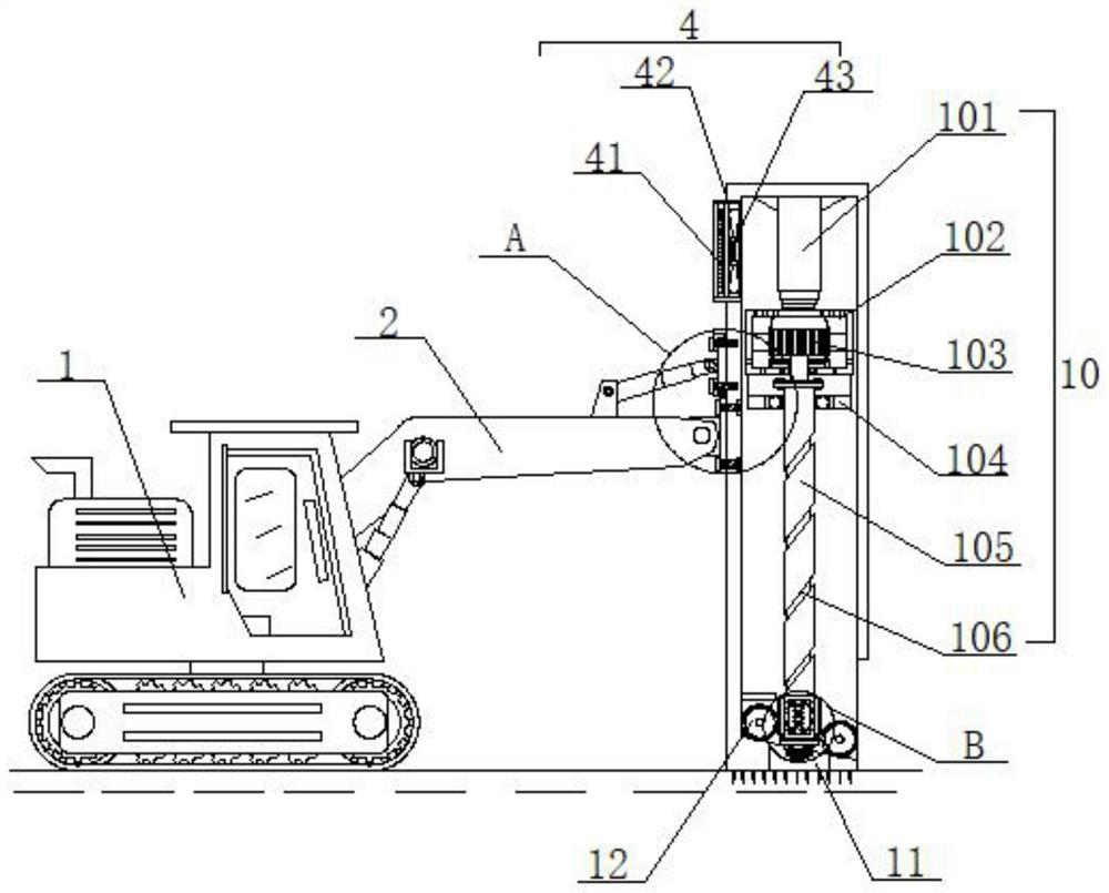
[0042] Example 2, such as figure 2 , 3 , 4 and 5, when starting to drill, the control panel on the excavator main body 1 controls the drive motor 103 to rotate, and the drive motor 103 drives the rotating rod 105 to rotate together, thereby driving the compact hole wall assembly 16 and the drill bit 17 Rotate, then control the telescopic hydraulic cylinder B101 to gradually extend, the drill bit 17 passes through the through groove 11 and starts to drill holes on the ground, the soil generated by the drilling is discharged to the inside of the main body compartment 5 along the spiral groove 106, and then the rotating motor 124 is controlled Rotate, because the two groups of guide rollers 123 are driven and connected by the cooperation of the pulley 121 and the transmission belt 122, the rotating motor 124 will drive the two groups of guide rollers 123 to rotate synchronously, so that the soil that will enter the bottom of the main body compartment 5 will gradually flow from t...

Embodiment 3

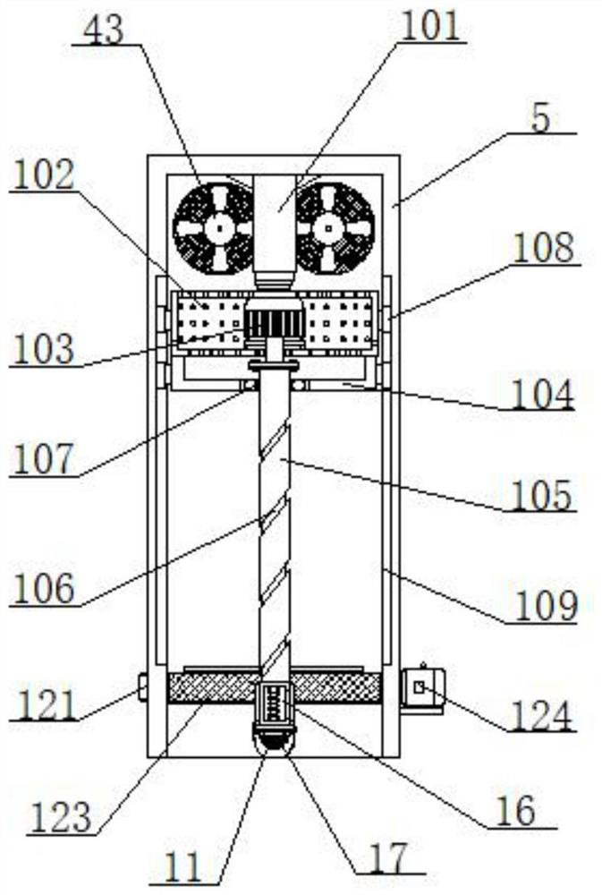
[0043] Example 3, such as figure 2 , 3 , 6 and 7, when the hole of the pile foundation is drilled, the driving motor 103 is controlled to speed up the speed greatly, thereby driving the installation warehouse 161 to rotate at an accelerated speed. The two sets of semi-arc scrapers 164 are opened outside the installation chamber 161, the two sets of sliding blocks 163 are close to each other, the spring 162 is shortened by force, and then the telescopic hydraulic cylinder B101 is controlled to shorten slowly, and the two sets of half-arcs rotated during the process The outside of the shaped scraper 164 constantly squeezes and polishes the inner wall of the hole. When the drill bit 17 is completely moved out of the hole, the driving motor 103 is controlled to stop rotating. 164 is tightly attached to the outside of the installation storehouse 161 again, and the inner wall of the hole has been compacted by the semi-arc scraper 164, so that no earth will fall into the hole on th...


PUM


Abstract

The invention provides a highway bridge pile foundation drilling device and a using method thereof. The highway bridge pile foundation drilling device comprises an excavator main body and a mechanicalarm, a main body bin is arranged at the end, away from the excavator main body, of the mechanical arm, a telescopic hydraulic cylinder A is arranged at the end, close to the main body bin, of the topof the mechanical arm, a clamping plate is arranged at the output end of the telescopic hydraulic cylinder A, and the end, close to the main body bin, of the clamping plate is fixedly connected withthe main body bin. Through cooperative use of the mechanical arm, the clamping plate, a sliding groove, a fixing screw, a buckle and a drill bit, the inclination angle of the main body bin can be freely adjusted, meanwhile, the rotating stability of the rotating rod is improved through a U-shaped support and a bearing, and the stability of the motor bin and the U-shaped support in the moving process is improved through a sliding block and the sliding groove; and the device can be adjusted to different inclination angles, so that the device can conveniently drill holes in the ground with different gradients, it is guaranteed that the holes of a pile foundation can reach the expected standard, and the quality of subsequent highway bridge construction is guaranteed.

Description

technical field [0001] The invention relates to the technical field of pile foundation drilling, in particular to a highway bridge pile foundation drilling device and a method for using the same. Background technique [0002] Pile foundation engineering is an engineering term. The construction of cast-in-situ piles is divided into two parts: hole formation and pile formation. Therefore, the inspection of pile foundations can be divided into two parts: hole formation quality inspection and pile formation quality inspection. The first link in pile construction. [0003] Most of the current pile foundation drilling devices are directly installed on the corresponding mechanical arms. Although it is possible to drill holes on ground with different slopes, during the drilling process, only relying on the mechanical arm for support cannot guarantee that the drilling device The stability during the drilling process cannot further improve the stability of the drilling device to ensu...

Claims


Application Information

Patent Timeline
IPC IPC(8): E21B7/02E21B15/00E21B21/16E21B3/02E21B7/00E21B12/06E21B41/00H02K9/04
CPCE21B3/02E21B7/005E21B7/02E21B12/06E21B15/00E21B21/16E21B41/00H02K9/04
Inventor 张德斌莫学雁李林杰
Owner 京山俊平机电科技有限公司
Why Eureka
Try Eureka