
Battery box cooling device

A cooling device and battery box technology, applied in secondary batteries, battery temperature control, battery pack components, etc., can solve the problems that the cooling effect cannot meet the requirements, the battery heats up, and affects the battery life, so as to improve the cooling efficiency. , Improve battery life, increase the effect of contact surface

Pending Publication Date: 2020-10-09
陈宜云
View PDF0 Cites 0 Cited by
  • Summary
  • Abstract
  • Description
  • Claims
  • Application Information

AI Technical Summary

Problems solved by technology

[0003] The battery will heat up during the working process, and the high temperature during the working process of the battery will affect the endurance of the battery. However, the cooling effect of the cooling device for the battery box in the prior art cannot meet the requirements. Therefore, it is necessary to design a battery box with a good cooling effect. cooling device

Method used


Image

  • Battery box cooling device
  • Battery box cooling device
  • Battery box cooling device

Examples


Embodiment 1

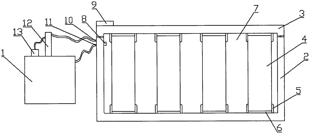
[0021] see figure 1 In Embodiment 1 of the present invention, a battery box cooling device includes a coolant tank 1 and a lower case 2, the interior of the coolant tank 1 is used to store coolant, and the lower case 2 is used to place a battery pack 4, The battery pack 4 is multiple groups, and the battery pack 4 is placed in the placement groove 5 on the lower case 2. This setting is convenient for fixing the battery pack 4 and improving the stability of the battery pack 4. A shock absorbing pad 6 is provided, and the shock absorbing pad 6 is provided so as to have a shock absorbing effect and improve the safety of the battery pack 4. The upper end cover of the lower case 2 is covered with an upper case 3, and both the lower case 2 and the upper case 3 are A first circulation channel is provided, and the two communicate with each other, and the lower shell 2 and the upper shell 3 are connected by bolts to ensure the stability of the connection.

[0022] The lower shell 2 is...

Embodiment 2

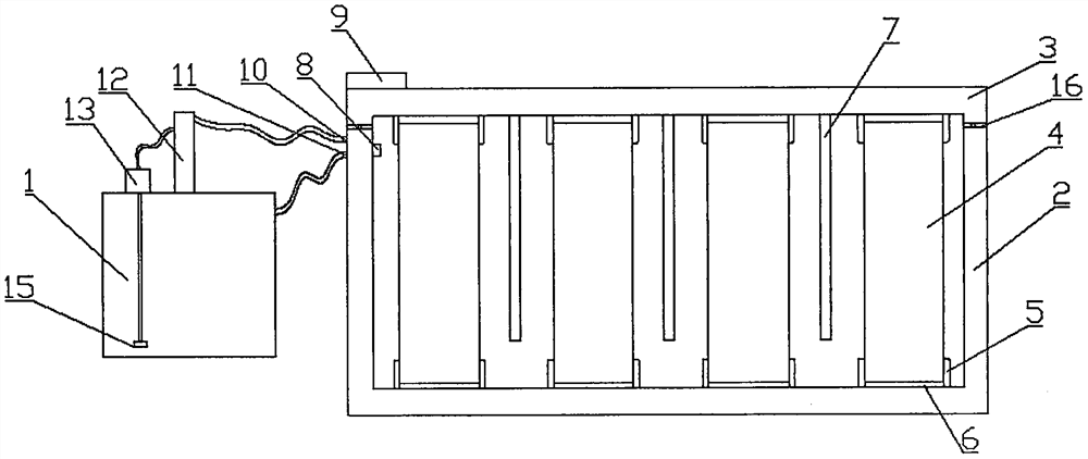
[0028] see Figure 2~3 The main difference between this embodiment 2 and embodiment 1 is that a gasket 16 is provided at the connection between the lower casing 2 and the lower casing 2, and the gasket 16 is set to prevent dust from entering the interior of the lower casing 2, and the two battery packs 4 are provided There is a heat exchange plate 7, and a second circulation flow channel 14 is arranged inside the heat exchange plate 7, and the second circulation flow channel 14 communicates with the first circulation flow channel inside the upper shell 3, and the heat exchange plate 7 is The continuous curved structure increases the contact surface between the heat exchange plate 7 and the hot air and improves the cooling efficiency.

[0029] The bottom of the output end of the water pump 13 is provided with a filter screen 15, and the filter screen 15 is arranged inside the coolant tank 1, and the filter screen 15 is provided to prevent the entire cooling system from being bl...


PUM


Abstract

The invention discloses a battery box cooling device, and relates to the technical field of batteries. The device comprises a cooling liquid tank and a lower shell; a battery pack is placed in the lower shell; the battery pack is placed in a placement groove in the lower shell; a shock pad is further arranged on the placement groove; the upper end of the lower shell is covered with an upper shell.The lower shell and the upper shell are each provided with a first circulating flow channel, and are communicated with each other; the lower shell and the upper shell are connected through a bolt. The lower shell is also provided with a water inlet and a water outlet; the water outlet is communicated with the cooling liquid tank, the water inlet is communicated with an outlet of the condenser, the inlet end of the condenser is connected to the outlet end of the water pump through a pipeline, the inlet end of the water pump is arranged in the cooling liquid tank, and the water inlet and the water outlet are communicated with the first circulating flow channel in the lower shell. The cooling effect is excellent, and the cooling efficiency is high.

Description

technical field [0001] The invention relates to the technical field of batteries, in particular to a battery box cooling device. Background technique [0002] A battery refers to a cup, tank or other container or part of a composite container that contains an electrolyte solution and a metal electrode to generate an electric current, and is a device that converts chemical energy into electrical energy. It has positive pole and negative pole. As technology advances, batteries generally refer to small devices that can generate electricity. Such as solar cells. The performance parameters of the battery mainly include electromotive force, capacity, specific energy and resistance. Using the battery as the energy source can obtain stable voltage, stable current, stable power supply for a long time, and a current that is little affected by the outside world, and the battery structure is simple, easy to carry, easy to charge and discharge, and is not affected by the external clim...

Claims


Application Information

Patent Timeline
Patent Type & Authority Applications(China)
IPC IPC(8): H01M2/10H01M10/613H01M10/63H01M10/635H01M10/6555H01M10/6567
CPCH01M10/613H01M10/63H01M10/635H01M10/6555H01M10/6567Y02E60/10
Inventor 陈宜云
Owner 陈宜云
Learn More