

Breathing machine
A ventilator and airbag technology, applied in the field of respiratory system, can solve the problems of high cost of oxygen supplementation, inability to supply at any time, and inconvenient use.
- Summary
- Abstract
- Description
- Claims
- Application Information
AI Technical Summary
Problems solved by technology
Method used
Image

Examples
Embodiment 1
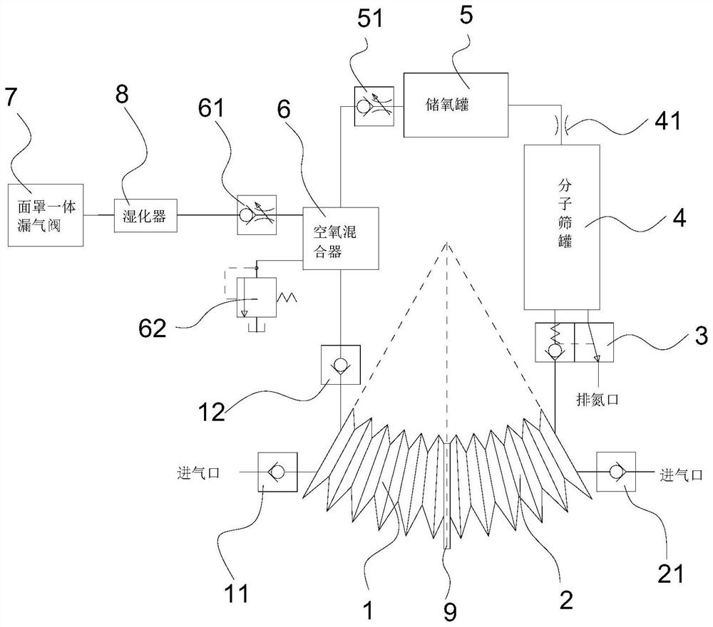
[0036] Such as figure 1 As shown, the ventilator includes a first airbag 1 and a second airbag 2 whose internal space can expand and shrink, a valve group, a molecular sieve tank 4, an oxygen storage tank 5, an air-oxygen mixer 6, and a mask integrated air leakage valve 7;
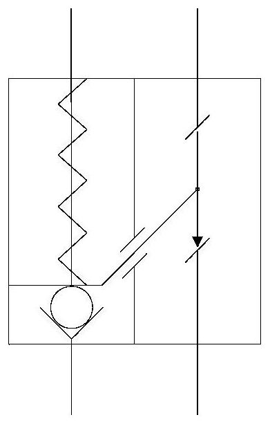
[0037]The first airbag 1 has an air inlet and an air outlet, the air inlet is provided with a first one-way valve 11, and the air outlet is provided with a third one-way valve 12, and the first airbag 1 is mixed with air and oxygen through the third one-way valve 12 The air-oxygen mixer 6 mixes the oxygen from the oxygen storage tank 5 and the air from the first air bag 1, and the air-oxygen mixer 6 is connected with the humidifier 8 through the second one-way throttle valve 61, and the humidifier 8 is connected with the mask integrated air leakage valve 7, and the air-oxygen mixer 6 is provided with an overflow valve 62 as a guarantee for exhalation safety.
[0038] The second airbag 2 has an air inlet a...
Embodiment 2
[0055] Such as Figure 5 As shown, the difference between this embodiment and embodiment one is that the number of molecular sieve tanks 4 is different:
[0056] In this embodiment, there are two molecular sieve tanks 4. Correspondingly, there are two two-position two-way linkage one-way pressure valves 3 and two throttle valves 41; a one-one two-way switching valve 42 is also included. After the second air bag 2 is connected to a one-position two-way switching valve 42, two two-position two-way linkage one-way pressure valves 3 are respectively connected, and the two-way linkage one-way pressure valve 3 is connected to a molecular sieve tank 4, and the top connection joint of the molecular sieve tank 4 Throttle valve 41, both throttle valves 41 are connected to oxygen storage tank 5.
[0057] Such as Figure 6(a) , 6(b) As shown, the one-position two-way switching valve 42 includes a touch lever 421, a return spring 422, a one-way gear 423, a first rack 424, and a two-posi...
Embodiment 3
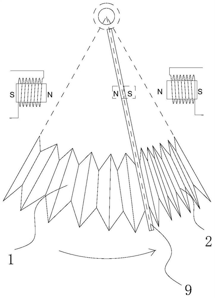
[0067] Such as Figure 8 , Figure 9 As shown, the difference between the present embodiment and the first embodiment lies in that the driving mode of the extruding plate 9 is different.
[0068] In this embodiment, the extruding plate 9 has a second rack 91 on the outside, and also includes a fixed driving gear 92 , and the second rack 91 meshes with the driving gear 92 .
[0069] Such as Figure 8 As shown, the driving gear 92 rotates clockwise, which drives the extrusion plate 9 to move to the right, compresses the second airbag 2, and expands the first airbag 1; Figure 9 As shown, the driving gear 92 rotates counterclockwise, driving the pressing plate 9 to move left, compressing the first airbag 1 and expanding the second airbag 2 .
[0070] In addition to realizing the left and right movement of the extrusion plate 9 through gear meshing, it can also be realized through mechanical structures such as chains, belts, and reciprocating screws.
PUM
 Abstract
Description
Claims
Application Information