Valve stent and interventional prosthetic heart valve

A valve and prosthesis technology, applied in the field of valve stents and interventional heart prosthetic valves, can solve the problems of poor stent fatigue performance, unstable anchoring, hindering left ventricular blood ejection, etc., to achieve strong anchoring force, not easy to slip or even shedding effect

Active Publication Date: 2020-10-13
UNIV OF SHANGHAI FOR SCI & TECH
View PDF11 Cites 0 Cited by
  • Summary
  • Abstract
  • Description
  • Claims
  • Application Information

AI Technical Summary

Problems solved by technology

[0004] An analysis of the traditional mitral / tricuspid prosthetic valve found that it has at least one of the following disadvantages: First, the "sharp corners" and "barbs" are easy to break, and the deformation direction of the "barbs" of traditional valves It is the same or opposite to the displacement direction of the valve stent, and the axial stress is also relatively large, so it is very prone to fracture; second, the anchoring is unstable at the initial postoperative stage, when the "barb" punctures the original leaflet annulus Finally, the human body will produce a phenomenon called "endothelialization": endothelial cells, etc. will gather near the wound, forming connective tissue to wrap the wound and "barbs", so that the "barbs" and the heart "integrate" to achieve Anchoring effect, but "endothelialization" usually takes about 3 months to complete, so in the early postoperative period, "endothelialization" has not been completed, the "barbs" are not stable enough, and the prosthetic valve is easy to loosen; third, the fatigue performance of the stent Poor; Fourth, LVOTO (left ventricular outflow track obstruction) occurs after mitral prosthetic valve intervention. The traditionally designed prosthetic valve has a large ventricular end, which will hinder the left ventricular contraction. Blood in the left ventricle is ejected from the aorta

Method used


Image

  • Valve stent and interventional prosthetic heart valve
  • Valve stent and interventional prosthetic heart valve
  • Valve stent and interventional prosthetic heart valve

Examples


Embodiment 1

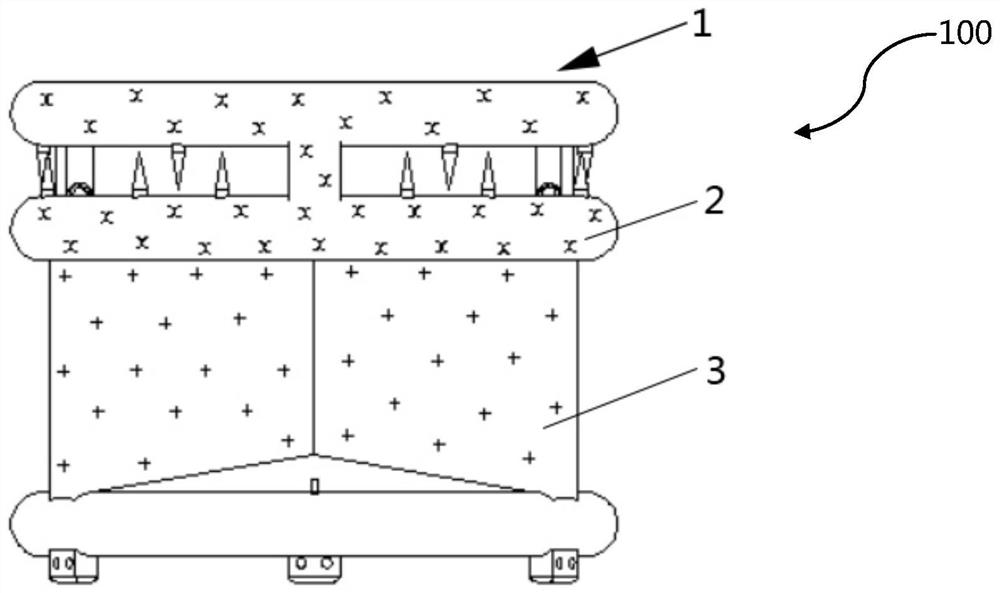
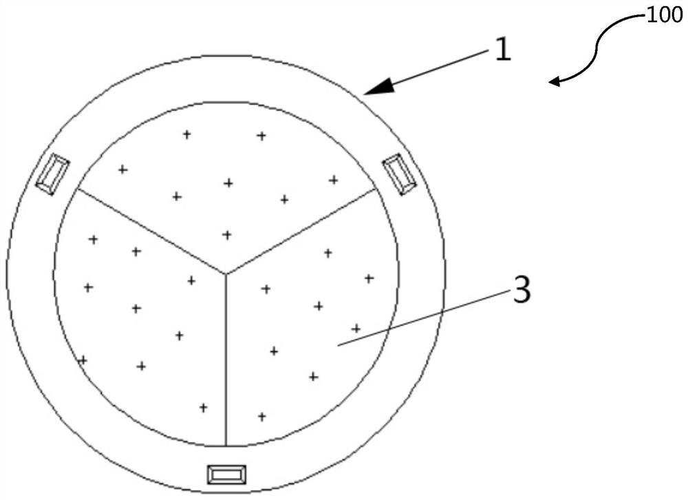
[0043] figure 1 It is a schematic front view of the three-dimensional structure of the prosthetic valve in Embodiment 1 of the present invention, figure 2 It is a schematic structural diagram of a three-dimensional top view of the prosthetic valve according to Embodiment 1 of the present invention;

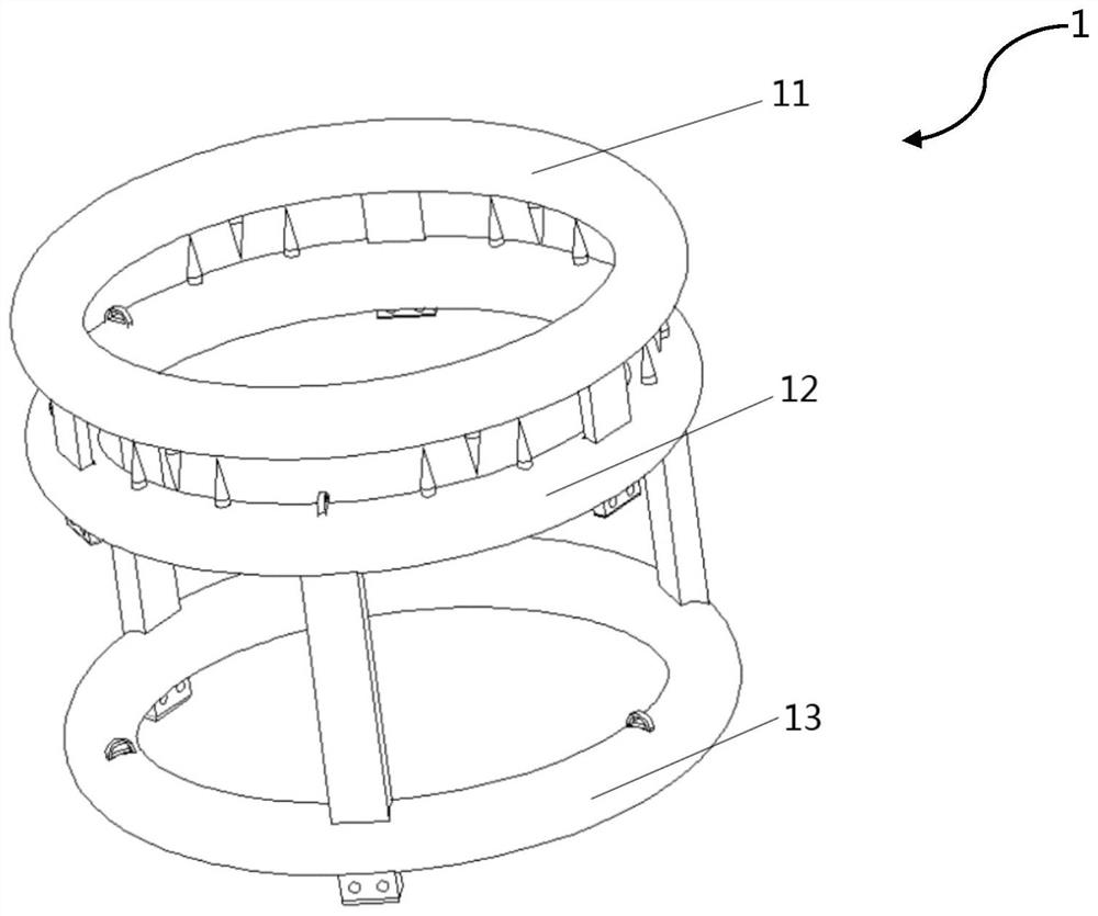
[0044] like figure 1 as well as figure 2 As shown, the interventional heart valve stent and prosthetic valve 100 of this embodiment has a valve stent 1 , a skirt 2 and an artificial valve leaflet 3 .

[0045] Wherein, the valve support 1 is a supporting and positioning structure of the prosthetic valve 100, and is used for carrying the artificial valve leaflet 3, attaching the skirt 2, anchoring and positioning, and the like. The valve stent 1 is made of shape memory alloy, which includes NiTi (nickel-titanium alloy), CuAlNi (copper-aluminum-nickel alloy) and the like. In this embodiment, the valve support 1 is made of NiTi.

[0046] For the convenience of description, the ...

Embodiment 2

[0121] In the present embodiment, the same structures as in the first embodiment are given the same reference numerals and the same descriptions are omitted.

[0122] Figure 20 It is a schematic diagram of the three-dimensional structure of the groove ring structure of the second embodiment of the present invention, Figure 21 It is a three-dimensional structure schematic diagram of the grooved ring structure of the second embodiment of the present invention after matching.

[0123] like Figure 21 As shown, the main difference between the present embodiment and the first embodiment is that the connection between the middle ring bracket 12 and the lower ring bracket 13 is not completed by the telescopic buckle 127 and the groove 134, but is connected by a grooved ring structure.

[0124] Specifically, the middle ring connecting rod 122 of this embodiment is I-shaped, and a plurality of continuous engagement protrusions 129 are arranged radially on the surface of the middle ...

Embodiment 3

[0130] In the present embodiment, the same structures as in the first embodiment are given the same reference numerals and the same descriptions are omitted.

[0131] Figure 25 It is a schematic diagram of the three-dimensional structure of the middle ring bracket of the third embodiment of the present invention, Figure 26 It is a cross-sectional structure diagram of the pulling ring of the third embodiment of the present invention.

[0132] Such as Figure 25 as well as Figure 26 As shown, the main difference between this embodiment and Embodiment 1 is that the pulling ring 126 of the middle ring is not in the shape of a raised semicircular ring, but is recessed in the middle ring 121, a through hole in a U-shaped structure, on the surface of the middle ring bracket 12 It is in the shape of two holes, and the pulling rope can pass through the U-shaped through hole through the two holes to complete the pulling effect. In this embodiment, the number of the middle ring pu...


PUM


Abstract

The invention aims to provide a valve stent with small volume, good fatigability and strong anchoring force and an interventional prosthetic heart valve. The valve stent is characterized by comprisingan upper ring stent, a middle ring stent located at one side of the upper ring stent, and a lower ring stent located on one side, far away from the upper ring stent, of the middle ring stent, whereinthe upper ring support is provided with an upper ring, upper ring connecting rods and upper ring barbs, the upper ring connecting rods and the upper ring barbs are arranged on the extending direction, towards the middle ring stent, of the upper ring; the middle ring support is provided with a middle ring, middle ring connecting rods, a middle ring connecting holes, middle ring barbs and middle ring traction rings; the middle ring connecting holes are evenly distributed in the middle ring and inserted by the corresponding upper ring connecting rods, so that the middle ring stent is connected with the upper ring stent, the middle ring connecting rods are arranged on the extending direction, towards the lower ring stent, of the middle ring, and the middle ring barbs are arranged on the extending direction, towards the upper ring stent, of the middle ring; and the lower ring support is provided with a lower ring, lower ring connecting holes and lower ring traction rings.

Description

technical field [0001] The invention belongs to the field of medical equipment, and relates to a valve support and an interventional heart prosthesis valve. Background technique [0002] Cardiac prosthetic valves are artificially manufactured organs that can be implanted in the heart to replace the original heart valves and control the one-way flow of blood in each chamber of the heart. With the development of the national economy and the aggravation of population aging, in recent years, the incidence of valvular heart disease has gradually increased, and the incidence population is also gradually younger. For patients with severe valvular disease who are elderly, complicated with multiple organ diseases, have a history of thoracotomy, and poor heart function, interventional treatment of valvular heart disease has many advantages such as no need for thoracotomy, less trauma, less pain, and faster recovery. , has been favored by more and more patients. [0003] Prosthetic v...

Claims


Application Information

Patent Timeline
Patent Type & Authority Applications(China)
IPC IPC(8): A61F2/24
CPCA61F2/2409A61F2/2412A61F2/2418A61F2/2436A61F2210/0014
Inventor 冒鹏志陈雨飞张德琪沈景凤
Owner UNIV OF SHANGHAI FOR SCI & TECH
Why Eureka
Try Eureka