Supercharge Your Innovation With Domain-Expert AI Agents!

Paint spaying device with drying function for industrial robot production

An industrial robot and functional technology, which is applied in the direction of spraying devices, liquid spraying devices, and devices for coating liquid on the surface, etc., can solve the problems of inconvenient fixing of robot parts of different specifications and low use range, so as to improve the fixing effect, Improve the stirring effect and prevent the effect of paint agglomeration

Inactive Publication Date: 2020-10-13
袁高宇
View PDF1 Cites 0 Cited by
  • Summary
  • Abstract
  • Description
  • Claims
  • Application Information

AI Technical Summary

Problems solved by technology

[0004] The above-mentioned patent also has the following disadvantages: when painting an industrial robot, it needs to be fixed according to the parts of the industrial robot of different shapes. The robot parts are fixed, resulting in a lower range of use of the device

Method used


Image

  • Paint spaying device with drying function for industrial robot production
  • Paint spaying device with drying function for industrial robot production
  • Paint spaying device with drying function for industrial robot production

Examples


Embodiment 1

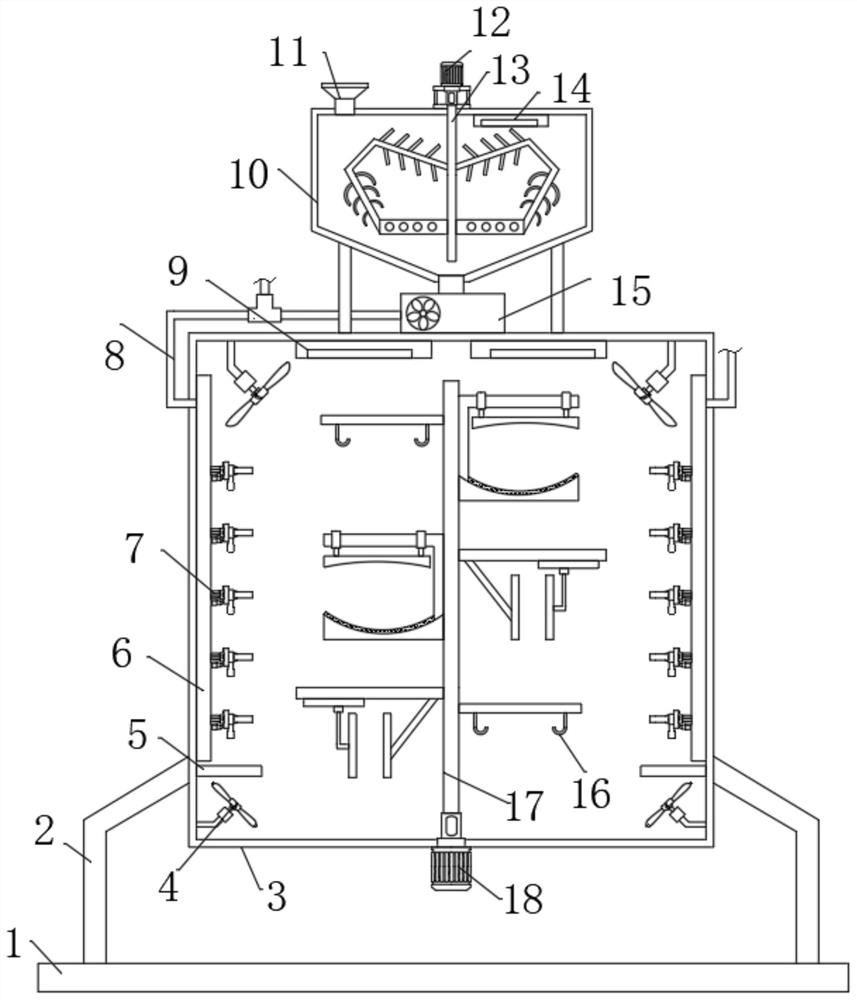
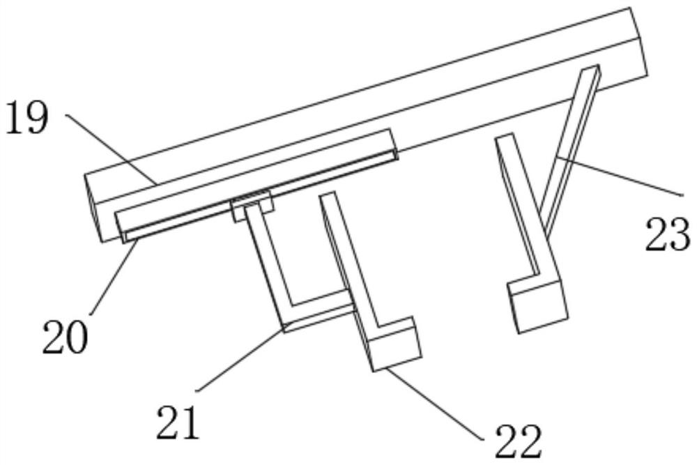
[0030] Reference Figure 1-4 , A paint spraying device for industrial robot production with drying function, comprising a bottom plate 1. The top and outer walls of the bottom plate 1 are welded with support legs 2 on both sides, and the other end of the support leg 2 is fixed with a spray paint box 3 by screws. The bottom outer wall of 3 is fixed with a second motor 18 by screws, and the output shaft of the second motor 18 is connected with a second rotating rod 17 through a coupling. The outer wall of the second rotating rod 17 is welded with a second fixing plate, and Hooks 16 are welded on both sides of the bottom outer wall of the fixing plate. Both sides of the outer wall of the second rotating rod 17 are fixed with a fixing plate 19 by screws. The bottom outer wall of the fixing plate 19 is fixed with a slide rail 20 by screws. A fixed rod 21 is slidably connected to the inner wall. The bottom outer wall of the fixed plate 19 is welded with a connecting rod 23. The other...

Embodiment 2

[0038] Reference Figure 5 , A paint spraying device for the production of industrial robots with drying function. Compared with the first embodiment, this embodiment also includes a temperature sensor 32 fixed to the inner wall of the top of the mixing box 10 by screws, and one side of the outer wall of the mixing box 10 is fixed by screws There is a display screen 33, and the signal input terminal of the display screen 33 is connected to the processor through a signal line, and the signal output terminal of the temperature sensor 32 and the signal input terminal of the processor are connected through a signal line.

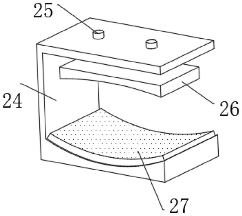
[0039] Connect the equipment to the power supply and choose the appropriate fixing according to the specifications of the industrial robot parts. The hook 16 can fix the parts with holes. The round parts can be placed on the fixing frame 24, and the hydraulic rod 25 can be connected to the hydraulic The system adjusts the length of the hydraulic rod 25 to make the c...


PUM


Abstract

The invention belongs to the technical field of industrial robots, in particular to a paint spraying device with a drying function for industrial robot production. According to the scheme provided forsolving the problem of poor fixing effect, the device comprises a bottom plate, supporting legs are arranged on the two sides of the outer wall of the top of the bottom plate, a paint spraying box isarranged at the other end of the supporting legs, a second motor is arranged on the outer wall of the bottom of the paint spraying box, an output shaft of the second motor is connected with a secondrotating rod through a coupler, a second fixing plate is arranged on the outer wall of the second rotating rod, hooks are arranged on the two sides of the outer wall of the bottom of the second fixingplate, and fixing plates are arranged on the two sides of the outer wall of the second rotating rod. The second fixing plate, the hooks, the fixing plates, sliding rails, fixing rods, clamping frames, fixing frames, hydraulic rods, clamping plates and antiskid layers are arranged, so that effective fixing can be carried out according to the specifications of parts of an industrial robot, and theparts with holes can be fixed by the hooks.

Description

Technical field [0001] The invention relates to the technical field of industrial robots, in particular to a paint spraying device for the production of industrial robots with a drying function. Background technique [0002] An industrial robot is a multi-joint manipulator or a multi-degree-of-freedom machine device oriented to the industrial field. It can perform work automatically. It is a machine that realizes various functions by its own power and control capabilities. It can accept human commands or follow The pre-programmed program runs. [0003] After searching, the Chinese patent grant number CN108787297B discloses a paint spraying device with drying function for the research and development of industrial robots. The following scheme is proposed, including a processing warehouse, the inner wall of the processing warehouse is equidistantly distributed Installation slot. [0004] The above-mentioned patents also have the following shortcomings: when painting industrial robots...

Claims


Application Information

Patent Timeline
Patent Type & Authority Applications(China)
IPC IPC(8): B05B16/20B05D3/04B05B13/02B05B15/25B05B9/04B05B12/10
CPCB05B9/0423B05B12/10B05B13/0228B05B13/0285B05D3/0413B05B15/25B05B16/20
Inventor 袁高宇
Owner 袁高宇
Features
  • R&D
  • Intellectual Property
  • Life Sciences
  • Materials
  • Tech Scout
  • Unparalleled Data Quality
  • Higher Quality Content
  • 60% Fewer Hallucinations
Learn More