Railway tunnel water discharging structure and construction technology thereof

A technology for tunnel drainage and construction technology, which is applied in drainage, safety devices, mining equipment, etc. It can solve the problems of heavy concrete pipes, poor anti-deformation ability of concrete pipes, and mud-flowing, etc., and achieves excellent tensile and bending properties. , excellent mechanical characteristics, and the effect of dispersing stress concentration

Pending Publication Date: 2020-10-13
RAILWAY ENG RES INST CHINA ACADEMY OF RAILWAY SCI
View PDF0 Cites 0 Cited by
  • Summary
  • Abstract
  • Description
  • Claims
  • Application Information

AI Technical Summary

Problems solved by technology

[0003] The drainage ditches of the existing tunnels are arranged on both sides of the tunnel lining. It is not only responsible for the drainage of various water in the tunnel, but also the water in the surrounding rock outside the tunnel is consciously allowed to flow into the tunnel and then drained away. This is not true. Reasonably, it cannot eliminate the water accumulation at the bottom of the tunnel foundation, and the tunnel drainage ditch cannot be leak-proof. Once the water leaks, it will just enter the tunnel bed, which provides good conditions for the occurrence of foundation bed diseases.
[0004] Moreover, most of the drainage ditches of existing tunnels use socket-type or prefabricated concrete pipes on site. Due to the heavy weight of the concrete pipes, large mechanical equipment is required for hoisting, and the construction progress is slow. In addition, the concrete pipes have poor deformation resistance. After the differential settlement of the tunnel base, the concrete pipes are prone to cracking, resulting in water leakage at the bottom of the tunnel, which will easily lead to subsidence and muddying at the bottom of the tunnel in the later stage

Method used


Image

  • Railway tunnel water discharging structure and construction technology thereof
  • Railway tunnel water discharging structure and construction technology thereof
  • Railway tunnel water discharging structure and construction technology thereof

Examples


Embodiment Construction

[0032] In the present invention, it should be understood that the terms "length", "width", "upper", "lower", "front", "rear", "left", "right", "vertical", "horizontal" ", "Top", "Bottom", "Inner", "Outer", "Clockwise", "Counterclockwise", "Axial", "Plane Direction", "Circumferential" and other indications are based on The orientation or positional relationship shown in the drawings is only for the convenience of describing the present invention and simplifying the description, and does not indicate or imply that the referred device or element must have a specific orientation, be constructed and operated in a specific orientation, and therefore cannot be understood as Limitations on the Invention.

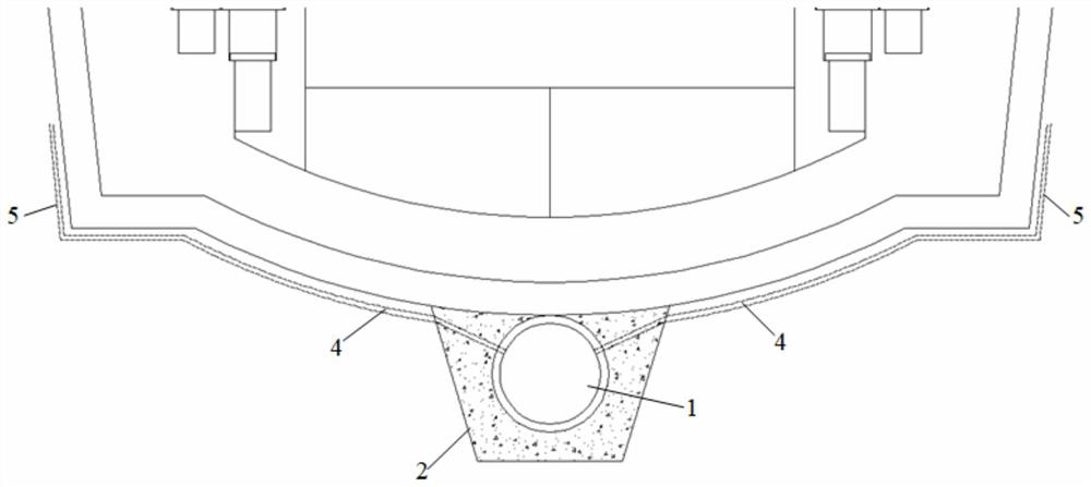
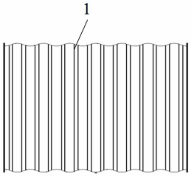
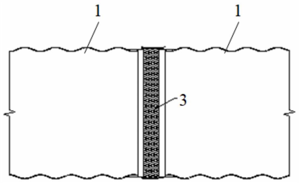
[0033] Such as Figure 1 to Figure 4 As shown, a railway tunnel drainage structure is characterized in that: it includes a side ditch and a deep drainage ditch in the center of the tunnel, the side ditch is arranged on both sides of the tunnel lining, and the deep drainage ditch in...


PUM


Abstract

The invention discloses a railway tunnel water discharging structure. Side ditches and a tunnel center deep water discharging ditch are included. The side ditches are arranged on the two sides of a tunnel lining. The tunnel center deep water discharging ditch is arranged below a tunnel bedding bottom or an inverted arch layer. The tunnel center deep water discharging ditch comprises a water discharging culvert pipe and a culvert pipe groove, and the water discharging culvert pipe is arranged in the culvert pipe groove. The tunnel center deep water discharging ditch is mainly used in the high rich water or underground water level and a cold-area railway tunnel, and a tunnel water discharging system is arranged below the tunnel bedding bottom or the inverted arch layer. During tunnel newly building, a deep water discharging ditch is constructed at a time, the integral stress of the inverted arch or bedding bottom layer is not influenced, the water discharging function is achieved for underground water rushing towards the periphery of the tunnel, underground water is gathered into the tunnel center deep water discharging ditch along the lining side wall or various blind ditches and gathering pipes, the underground water level can be lowered through the tunnel center deep water discharging ditch, the underground water level is located below a base by a certain height, dryness of atunnel bottom ballast bed is guaranteed, and the water erosion influences are avoided. A water discharging structure construction technology is further disclosed.

Description

technical field [0001] The invention belongs to the technical field of railway tunnels, and in particular relates to a railway tunnel drainage structure and a construction process thereof. Background technique [0002] With the construction of a large number of railway tunnels in my country, more and more tunnel bases have suffered from frost heave, heaving, and slurry and mud leakage. The survey shows that the mud-flushing disease often occurs under the track bed of railway tunnels with rich groundwater, especially for tunnels with a length of more than 6km and the integral track bed. Restricted by harsh conditions such as difficult maintenance, it is extremely difficult to control and eradicate; in addition, railway tunnels in cold regions are affected by cold climates, and are prone to periodic freeze-thaw cycles. It is easy to cause diseases such as ice hanging on the tunnel lining, ice accumulation on the track bed, and floor heaving, which seriously endangers driving ...

Claims


Application Information

Patent Timeline
Patent Type & Authority Applications(China)
IPC IPC(8): E21F16/02
CPCE21F16/02
Inventor 马伟斌郭小雄付兵先邹文浩李尧王志伟刘勇刘阔誉杜晓燕安哲立赵鹏马超锋程爱君李秋菊张森
Owner RAILWAY ENG RES INST CHINA ACADEMY OF RAILWAY SCI
Why Eureka
Try Eureka