
Braiding equipment for cable and process thereof

A cable and equipment technology, which is applied in the field of cable braiding equipment and its technology, can solve problems affecting cable performance and periodic changes in cable braiding structure, and achieve the effects of reducing regular reflection and optimizing voltage standing wave ratio

Pending Publication Date: 2020-10-13
SHENZHEN SUPERLINK TECH CO LTD
View PDF1 Cites 2 Cited by
  • Summary
  • Abstract
  • Description
  • Claims
  • Application Information

AI Technical Summary

Problems solved by technology

[0004] In view of the above-mentioned related technologies, the inventor believes that there are the following defects: in order to ensure the smooth and stable weaving of the coaxial cable, the take-up reel often rotates at a constant speed to rewind the cable, but in the actual winding process, the take-up device is due to Factors such as dimensional accuracy inevitably produce periodic vibrations, which will lead to periodic changes in the cable braiding structure, resulting in regular periodic changes in the characteristic impedance of the cable
When transmitting radio frequency signals, the reflection caused by impedance mismatch will be periodically superimposed on a fixed frequency, so that the VSWR will have a high peak at certain frequencies, which will affect the performance of the cable

Method used


Image

  • Braiding equipment for cable and process thereof
  • Braiding equipment for cable and process thereof
  • Braiding equipment for cable and process thereof

Examples


Embodiment Construction

[0037] The following is attached Figure 1-4 , to further describe this application in detail.

[0038] The embodiment of the present application discloses a cable braiding device.

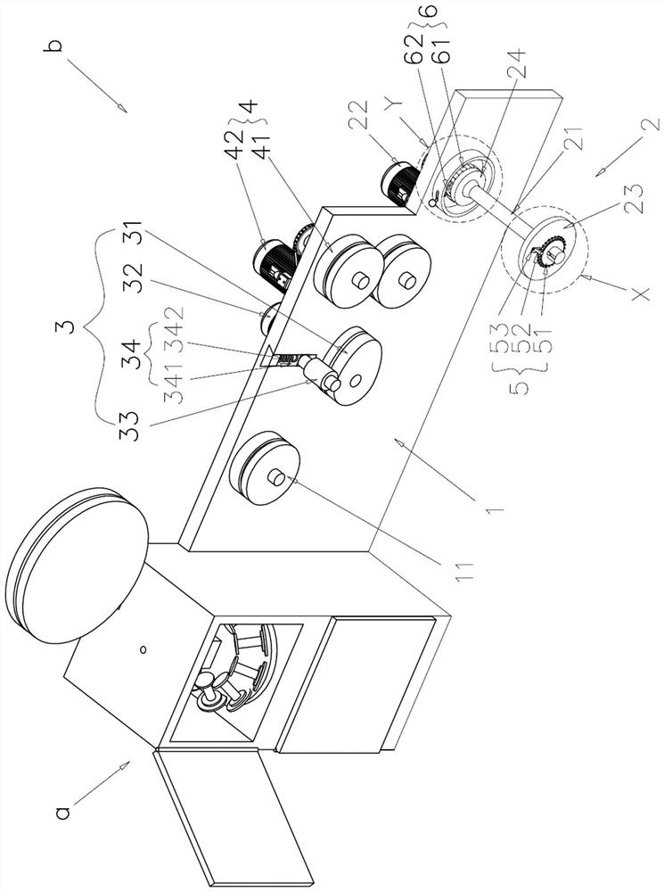
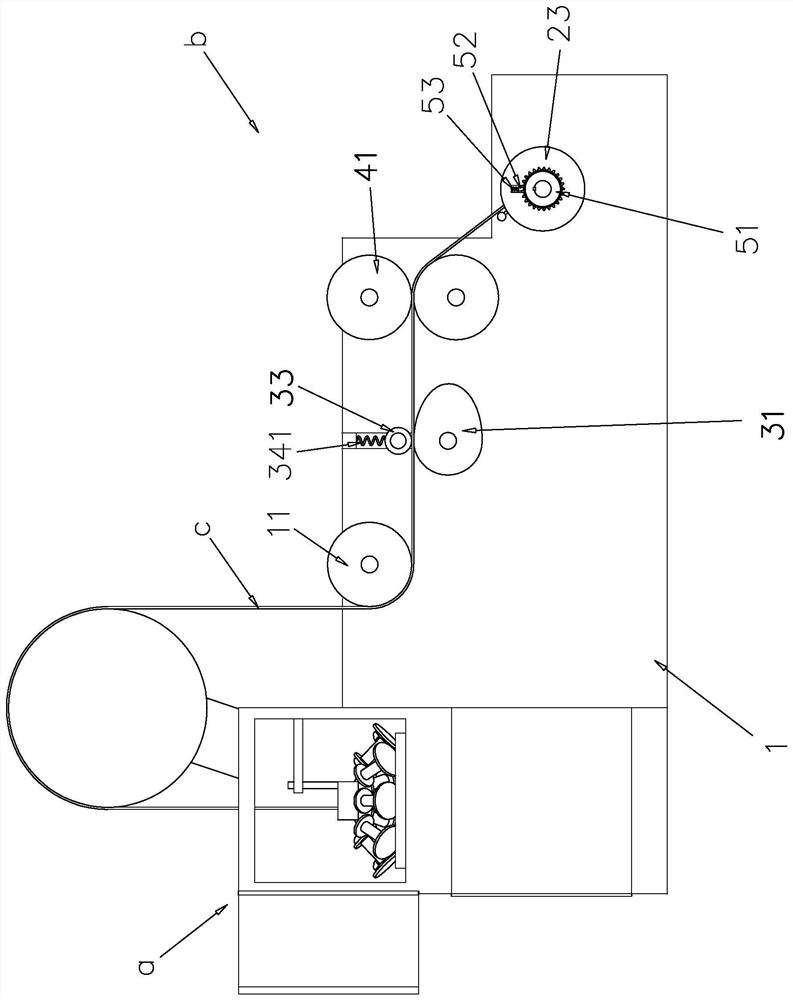
[0039] refer to figure 1 and figure 2 , a braiding device for cables includes a braiding machine body a and a wire take-up device b connected to the braiding machine body a, the braiding machine body a is used to braid the cable shielding layer to form a cable c, and the wire take-up device b is used to wind up the cable c Pulling force is applied to the cable c braided on the braiding machine body a, thereby driving the cable c to move.

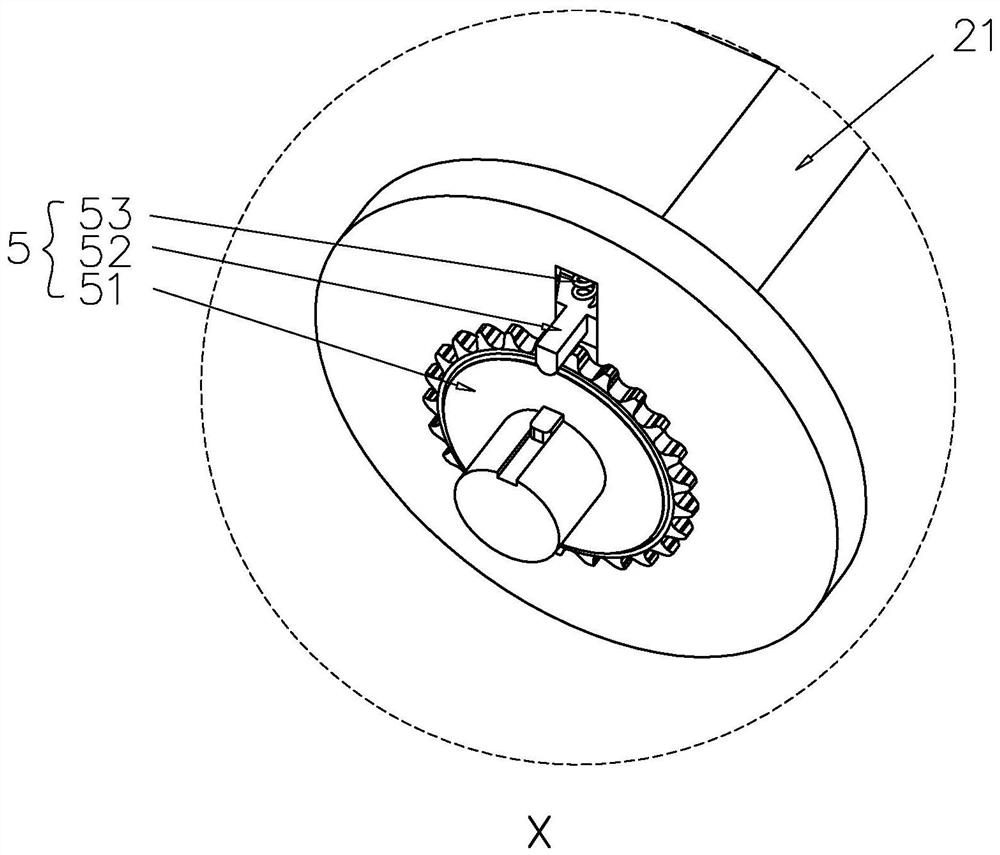
[0040] The take-up device b includes a base frame 1 connected to the braiding machine body a, a speed regulating mechanism 3 for adjusting the moving speed of the cable c, a stabilizing conveying mechanism 4 for stabilizing the conveying speed of the cable c, and a retracting mechanism for winding the cable c. Volume Mechanism 2. The stable conveying mecha...


PUM


Abstract

The application relates to braiding equipment for a cable and a process thereof. The braiding equipment for the cable comprises a braiding machine body and a take-up device. The take-up device comprises a base frame, a take-up mechanism and a speed adjusting mechanism used for adjusting the moving speed of the cable; the speed adjusting mechanism is arranged on the side, close to the braiding machine body, of the take-up mechanism; the speed adjusting mechanism comprises a direction adjusting cam, the direction adjusting cam is in an irregular oval shape and is rotationally connected with thebase frame, and the outer edge face of the direction adjusting cam abuts against and is attached to the cable. The outer edge surface of the direction adjusting cam is attached to the cable so as to guide the moving speed of the cable; when the direction adjusting cam rotates, the moving direction of the cable is changed along with the rotation of the direction adjusting cam; the change of the moving direction of the cable changes the moving speed of the cable, thereby driving the structure of the cable braided shielding layer to change, destroying the periodic change of the characteristic impedance of the cable in the braiding process, reducing the regular reflection of electromagnetic waves in the cable, and optimizing the voltage standing-wave ratio of the coaxial cable.

Description

technical field [0001] The present application relates to the technical field of coaxial cable production, in particular to a cable braiding device and a process thereof. Background technique [0002] Coaxial cables are high-precision electronic components that can be used in radar systems, electronic countermeasure systems, and electronic measurement systems. The voltage standing wave ratio of the coaxial cable is one of the important indicators to measure the electrical performance of the coaxial cable. Voltage standing wave ratio refers to the sum of reflected signals caused by impedance mismatch when transmitting radio frequency signals. This index determines the fit of the coaxial cable in the entire electronic system, which means that the voltage standing wave ratio directly determines the quality level of the RF coaxial cable. [0003] The shielding layer production of coaxial cables is often carried out by braiding process. With reference to the utility model pate...

Claims


Application Information

Patent Timeline
IPC IPC(8): H01B13/22H01B13/26
CPCH01B13/225H01B13/228H01B13/2606
Inventor 罗汉飞张麟乔全宝
Owner SHENZHEN SUPERLINK TECH CO LTD
Learn More