Warp knitting machine yarn path distributing system

A distribution system and warp knitting machine technology, applied in warp knitting, textiles, papermaking, knitting, etc., can solve the problems of unreasonable distribution of yarn paths and poor warp knitting quality of warp knitted fabrics, and improve service life and stability. Good, avoid the effect of resonance

Pending Publication Date: 2020-10-16
JINJIANG PENGTAI MACHINERY TECH CO LTD
View PDF1 Cites 0 Cited by
  • Summary
  • Abstract
  • Description
  • Claims
  • Application Information

AI Technical Summary

Problems solved by technology

[0004] Therefore, in view of the above-mentioned problems, the present invention provides a warp knitting machine yarn path system, which mainly solves the problem that the yarn path distribution in the prior art is unreasonable and causes the warp knitting quality of warp knitted fabrics to be poor.

Method used


Image

  • Warp knitting machine yarn path distributing system
  • Warp knitting machine yarn path distributing system
  • Warp knitting machine yarn path distributing system

Examples


Embodiment Construction

[0021] The present invention will now be further described with reference to the accompanying drawings and specific embodiments.

[0022] The embodiment of the present invention is:

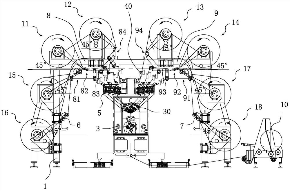
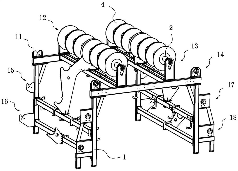
[0023] refer to figure 1 and figure 2As shown, a yarn path distribution system of a warp knitting machine includes a frame 1, eight rotating shafts 2 rotatably arranged on the frame 1, a driving motor (not shown in the figure) for driving the rotating shafts 2 to rotate, and a warp knitting machine. Device 3, the warp knitting machine has a bar assembly 30, each of the rotating shafts 2 is provided with six disk heads 4, the upper part of the warp knitting device 3 is provided with a yarn guide compensation mechanism 5, which defines the direction along the warp knitting device 3 The length direction of the warp knitting device 3 is defined as the front-rear direction, the height direction of the warp knitting device 3 is defined as the up-down direction, and the width direction of the warp kn...


PUM


Abstract

The invention relates to the field of textile machinery, in particular to a warp knitting machine yarn path distributing system, and mainly aims to solve the problem in the prior art that yarn path distribution is not reasonable to cause that the warp knitting quality of warp knitting fabric is poor. The warp knitting machine yarn path distributing system comprises a rack, seven or eight rotary shafts rotatably arranged on the rack, a drive motor driving the rotary shafts to rotate, and a warp knitting device; a plurality of pan heads are arranged on each of the rotary shafts; a yarn guiding compensating mechanism is arranged at the upper part of the warp knitting device; the rack covers the outer side of the warp knitting device; the rotary shafts are arranged on the rack in parallel in the front-rear direction; eight yarn placing areas including a first yarn placing area, a second yarn placing area, a third yarn placing area, a fourth yarn placing area, a fifth yarn placing area, a sixth yarn placing area, a seventh yarn placing area and an eighth yarn placing area for mounting all rotary shafts are arranged on the rack; and a yarn tension adjusting device for adjusting the tension of the yarn on each yarn placing area is arranged between the rack and the yarn guiding compensating mechanism.

Description

technical field [0001] The invention relates to the field of textile machinery, in particular to a yarn path distribution system for a warp knitting machine. Background technique [0002] The warp knitting machine uses one or several groups of parallel yarns to feed all the working needles of the machine in the warp direction, while the machine forms a loop to form a knitted fabric, specifically, including the frame and the warp knitting device, the frame setting. On the peripheral side of the warp knitting device, several rotating shafts are arranged on the frame in parallel and rotatable, and the rotating shafts are driven to rotate by a driving motor, and a plurality of coil heads wound with yarn are arranged on each of the rotating shafts. The warp knitting device includes a loop forming The device, the bar device, and the transmission device, wherein the loop forming device comprises symmetrical front and rear loop-off parts, symmetrical front and rear needle bed parts ...

Claims


Application Information

Patent Timeline
Patent Type & Authority Applications(China)
IPC IPC(8): D04B27/24D04B27/10
CPCD04B27/10D04B27/24
Inventor 王俊雄王启超陈浩覃明闪王志强
Owner JINJIANG PENGTAI MACHINERY TECH CO LTD
Why Eureka
Try Eureka