
Electronic throttle valve and control method suitable for mild HEV

An electronic throttle valve and control method technology, applied in electrical control, engine control, fuel injection control and other directions, can solve the problems of unsatisfactory ice breaking effect, shortened service life, large damage to the disc shaft, etc., to achieve high promotion and use value, increase Rotating torque, long service life effect

Active Publication Date: 2020-10-16
CHANGCHUN UNIV OF SCI & TECH
View PDF18 Cites 0 Cited by
  • Summary
  • Abstract
  • Description
  • Claims
  • Application Information

AI Technical Summary

Problems solved by technology

However, since the HEV light hybrid vehicle engine works in the economic zone for a long time, the heat dissipation of the engine is lower, and the water content of the exhaust gas is higher (EGR system engine is affected by the exhaust gas), this characteristic aggravates the tendency of the throttle valve to freeze
The electronic throttle of traditional engines relies on the disc position sensor. When the actual position of the disc is inconsistent with the target position, the throttle valve is judged to be faulty and the engine fault code is output. The disc generates the maximum torque to break the ice. Firstly, the ice breaking effect is not ideal, and secondly, it will cause great damage to the disc shaft and reduce the service life.
[0004] Therefore, in order to solve the problem that the traditional electronic throttle is easy to freeze when it is turned off for a long time in winter, resulting in the failure of the vehicle to start smoothly, it is urgent to optimize and improve the electronic throttle to improve its ice-breaking ability, so that the vehicle can start and drive normally in winter

Method used


Image

  • Electronic throttle valve and control method suitable for mild HEV
  • Electronic throttle valve and control method suitable for mild HEV
  • Electronic throttle valve and control method suitable for mild HEV

Examples


Embodiment Construction

[0023] The technical solutions in the present invention will be clearly and completely described below in conjunction with the accompanying drawings in the embodiments of the present invention. Obviously, the described embodiments are only part of the embodiments of the invention, not all of them. Based on the present invention All other embodiments obtained by persons of ordinary skill in the art without creative efforts, all belong to the scope of protection of the present invention.

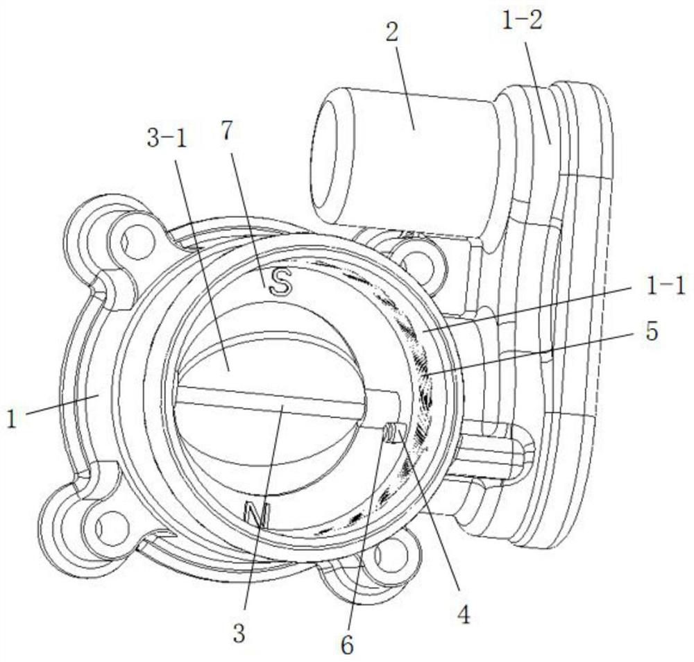
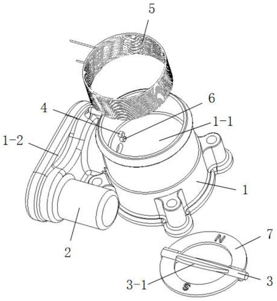
[0024] Such as Figure 1 ~ Figure 2 As shown, an electronic throttle valve suitable for HEV mild hybrid vehicles includes a throttle housing 1, a drive motor 2, a disc shaft 3, an electromagnetic coil 5, an icing sensor 6 and a permanent magnet outer disc 7. The valve housing 1 is connected end to end with a valve hole 1-1 and a motor installation cavity 1-2 is integrally provided outside the tail end, the disc shaft 3 is arranged radially in the valve hole 1-1 and its two ends are respectivel...


PUM


Abstract

The invention discloses an electronic throttle valve and a control method suitable for a mild HEV, and relates to an electronic throttle valve and a control method. A throttle valve shell is providedwith a valve hole, the tail end of the throttle valve shell is provided with a motor mounting cavity, a disc shaft is arranged in the valve hole in the radial direction and is rotationally connected with the valve hole, an inner disc is integrally arranged in the middle of the disc shaft, and a driving motor is fixed in the motor mounting cavity. An output shaft is fixedly provided with a drivinggear which meshes with a driven gear fixed at the end of the disc shaft to control rotation of the disc shaft. A temperature sensor is fixed to the inner wall of the valve hole, the driven gear is provided with a rotation angle sensor and a return spring, a permanent magnetic outer disc is annularly arranged between the inner disc and the inner wall of the valve hole and provided with a sleeve which is rotationally connected with the disc shaft at the two ends of the inner disc, and an electromagnetic coil and an icing sensor are adjacent to the permanent magnetic outer disc and fixed to the inner wall of the valve hole. The electromagnetic coil is additionally arranged, and the inner disc and the permanent magnetic outer disc are assembled into a combined disc, so that the deicing effectis better, and the service life is longer.

Description

technical field [0001] The invention relates to an electronic throttle and a control method, in particular to an electronic throttle and a control method suitable for HEV light hybrid vehicles, and belongs to the technical field of vehicle air intake systems. Background technique [0002] The electronic throttle is an important control part of the car engine. When the driver steps on the accelerator pedal, he is actually adjusting the opening of the throttle, and the adjustment of the opening of the throttle is realized by adjusting the rotation angle of the disc. Step on the accelerator pedal deeply and the throttle opening will increase, the intake air volume and fuel injection volume will increase, and the engine output power and torque will increase, and vice versa. [0003] In winter in the north, especially after snow and high humidity conditions, due to the process of condensation and freezing of water vapor, the condensed water flows down along the wall of the thrott...

Claims


Application Information

Patent Timeline
IPC IPC(8): F02D41/00F02D11/10F02N19/02
CPCF02D41/0002F02D11/10F02D11/107F02N19/02F02D2041/0022F02D2011/101Y02T10/40
Inventor 王永华韩雪峰于化东许金凯李学光于占江任万飞弯艳玲
Owner CHANGCHUN UNIV OF SCI & TECH
Features
  • Generate Ideas
  • Intellectual Property
  • Life Sciences
  • Materials
  • Tech Scout
  • Unparalleled Data Quality
  • Higher Quality Content
  • 60% Fewer Hallucinations
Learn More