
Double-tube flyback power supply circuit

A power circuit, dual-tube flyback technology, applied in electrical components, adjusting electrical variables, instruments, etc., can solve the problems of bulky inverter products, complex systems, and high costs, reducing weight and volume, and reducing system complexity. , The effect of improving installation efficiency

Inactive Publication Date: 2020-10-16
SHENZHEN SINE ELECTRIC
View PDF6 Cites 1 Cited by
  • Summary
  • Abstract
  • Description
  • Claims
  • Application Information

AI Technical Summary

Problems solved by technology

[0003] The purpose of the present invention is to provide a dual-tube flyback power supply circuit to solve the problems of heavy frequency converter products, large volume, high cost, and complex systems caused by the introduction of a power frequency transformer in the prior art

Method used


Image

  • Double-tube flyback power supply circuit
  • Double-tube flyback power supply circuit
  • Double-tube flyback power supply circuit

Examples


Embodiment Construction

[0030] In order to have a clearer understanding of the technical features, purposes and effects of the present invention, the specific implementation manners of the present invention will be described in detail below with reference to the accompanying drawings. It should be understood that the following descriptions are only specific illustrations of the embodiments of the present invention, and should not limit the protection scope of the present invention.

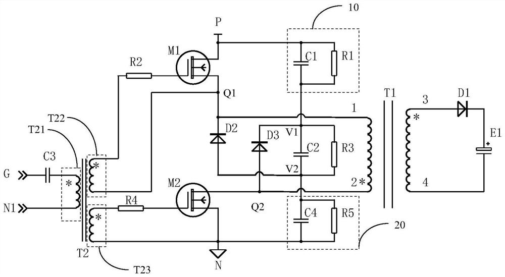
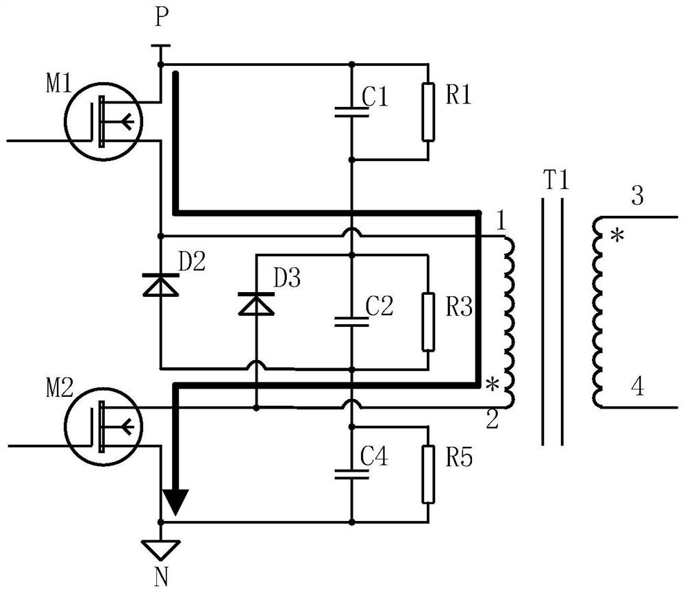
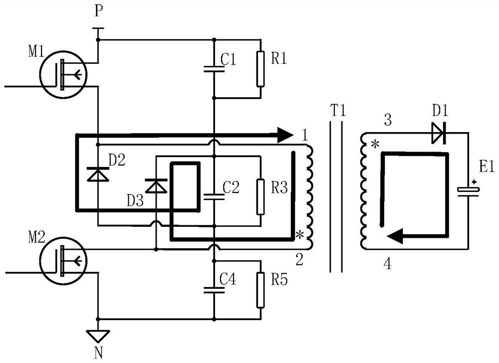
[0031] see figure 1 , figure 1 A schematic diagram of the structure of a dual-tube flyback power supply circuit provided by an embodiment of the present invention, the dual-tube flyback power supply circuit includes a flyback transformer T1, a first MOS transistor M1, a second MOS transistor M2, a first diode D2 , the second diode D3 , the absorption capacitor C2 , the first auxiliary voltage equalizing circuit 10 and the second auxiliary voltage equalizing circuit 20 .

[0032] One end 1 of the primary coil of the fly...


PUM


Abstract

The invention discloses a double-tube flyback power supply circuit, which comprises: a flyback transformer, wherein one end of the primary side coil of the flyback transformer is connected to a firstnode, and the other end of the primary side coil of the flyback transformer is connected to a second node; a first MOS tube, wherein the source electrode of the first MOS tube is connected to the first node, and the drain electrode of the first MOS tube is connected to a first direct-current bus end; a second MOS tube, wherein the source electrode of the second MOS tube is connected to a second direct-current bus end, and the drain electrode of the second MOS tube is connected to the second node; a first diode, wherein the cathode of the first diode is connected to the first node, and the anode of the first diode is connected to a fourth node; a second diode, wherein the anode of the second diode is connected to the second node, and the cathode of the second diode is connected to a third node; an absorption capacitor, wherein one end of the absorption capacitor is connected to the third node, and the other end of the absorption capacitor is connected to the fourth node; a first auxiliary voltage-sharing circuit; and a second auxiliary voltage-sharing circuit.

Description

technical field [0001] The invention relates to the technical field of a flyback power supply with middle clamping, in particular to a double-tube flyback power supply circuit. Background technique [0002] The frequency converter is a device that uses a fixed input voltage and frequency power supply to control the switch of the power electronic power device to adjust the output voltage amplitude and frequency to achieve motor speed regulation. In the frequency converter, multiple isolated power supplies are required due to the drive control of various power electronic devices, the conditioning of multiple analog signals, and the processing of digital signals. For inverters with a voltage level of 380V, it is generally necessary to design a multi-output flyback power supply to meet the cross-regulation rate, cost and volume requirements. However, for a medium-voltage inverter with a voltage level of 660V, its rated bus voltage is nearly 1,000 volts, plus the fluctuation of ...

Claims


Application Information

Patent Timeline
IPC IPC(8): H02M3/335
CPCH02M3/3353
Inventor 甘帅涂从欢张晓光何畏
Owner SHENZHEN SINE ELECTRIC
Learn More