Traction instrument for ESD (endoscopic submucosal dissection) surgery
An instrument and surgery technology, applied in the field of ESD surgical traction instruments, can solve the problems of difficult operation process, difficult to grasp accurately, move and direction control, etc.
- Summary
- Abstract
- Description
- Claims
- Application Information
AI Technical Summary
Problems solved by technology
Method used
Image
Examples
Embodiment 1
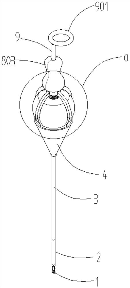
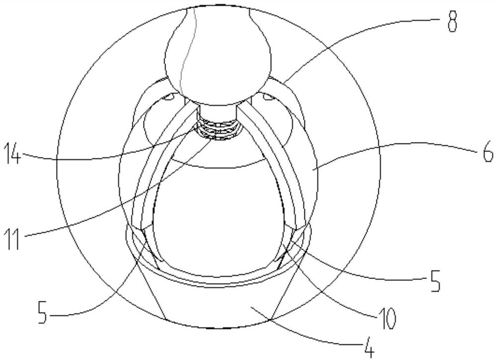
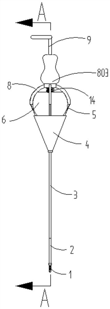
[0036] Embodiment 1, a kind of ESD operation traction apparatus, such as Figure 1-6 As shown, it includes guide handle 9, upper cover 8, guide ball 6, outer sleeve 3, guide tube 2 and pulling clamp 1; outer sleeve 3, guide tube 2 and pulling clamp 1 are sequentially connected in the axial direction, and guide ball 6 It is fixedly connected with the outer sleeve 3, the upper cover 8 is set on the outer circumference of the guide ball 6, and rotates along the spherical surface of the guide ball 6; the guide handle 9 is connected with a push-pull cable 11, and the push-pull cable 11 passes through the gland 802 sequentially in the axial direction , the guide ball 6, the outer casing 3 and the guide tube 2 are connected with the pull clip 1, and the guide handle 9 can move back and forth along the axial direction of the push-pull cable 11; 5 is connected with the end of the guide tube 2 across the guide ball 6 along the outer circumference of the guide ball 6 .
[0037] The guid...
Embodiment 2
[0044] In Embodiment 1, the pulling wire 5 is located on the surface of the guide ball 6. In order to avoid interference with the ball 13, the pulling wire 5 needs to be fixed on the lower part of the upper cover 8, that is, the connection points of each pulling wire 5 on the upper cover 8 are different, and welding It is difficult to find a point. For this reason, this embodiment improves the setting position of the drawing wire 5, and at the same time, the spherical rotation of the upper cover 8 and the guide ball 6 is also changed accordingly: as Figure 7-Figure 10 As shown, the upper cover 8 includes a gland 802 and a clamping cover 7 fixed to the bracket 4. The clamping cover 7 can ensure that the upper cover 8 does not separate from the guide ball 6. Specifically, it ensures that the gland 802 does not separate from the guide ball. 6, the card cover 7 is covered on the outer periphery of the gland 802. At this time, there is no need to additionally set a radial limit str...
Embodiment 3
[0046] On the basis of Example 2, such as image 3 and Figure 9 As shown, the traction handle 801 also includes a guide column 803 arranged at the upper end, the guide column 803 protrudes from the outer surface of the hemispherical traction handle 801, and is in the shape of a hollow column as a whole, the lower part of the guide handle 9 is suitable for passing through the guide column 803, and reciprocate along the axial direction of the guide column 803 . The central hole of the guide column 803 is adapted to the lower part of the guide handle 9, and is used for radially limiting the guide handle 9 to prevent the guide handle 9 from shaking, for example, it is arranged to abut and cooperate with each other. Such as Figure 6 and Figure 9 As shown, the central hole of the guide column 803 is also provided with an upper boss 8031 that cooperates with the lower boss 902 of the guide handle 9. The outer diameter of the lower boss 902 is greater than the inner diameter o...
PUM
 Abstract
Description
Claims
Application Information
 - R&D
- Intellectual Property
- Life Sciences
- Materials
- Tech Scout
- Unparalleled Data Quality
- Higher Quality Content
- 60% Fewer Hallucinations
Browse by: Latest US Patents, China's latest patents, Technical Efficacy Thesaurus, Application Domain, Technology Topic, Popular Technical Reports.
© 2025 PatSnap. All rights reserved.Legal|Privacy policy|Modern Slavery Act Transparency Statement|Sitemap|About US| Contact US: help@patsnap.com


