

Bar double-end-face drilling device and method
A drilling device and double-face technology, applied in drilling/drilling equipment, positioning devices, boring/drilling, etc., can solve problems such as difficulty in ensuring the coaxiality of the two end faces, poor clamping, etc.
- Summary
- Abstract
- Description
- Claims
- Application Information
AI Technical Summary
Problems solved by technology
Method used
Image

Examples
Embodiment 1
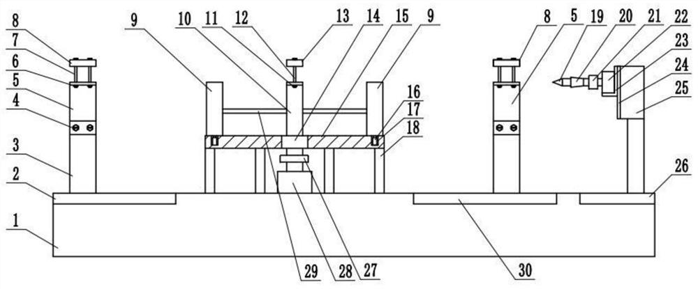
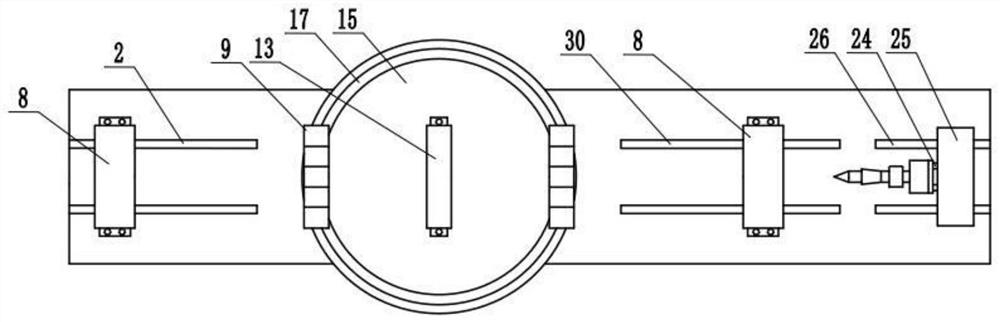
[0035] The support unit includes a turntable 15, an intermediate support 10, a rotating unit and two side supports 9. A ring groove 17 is cut on the turntable 15. The middle support 10 is penetrated and fixed in the center of the turntable 15 through a bearing 14. The two side supports 9 are fixed along the turntable 15. The diameter is installed on both sides of the middle support 10, the middle support 10 and the side support 9 are of the same height, the middle support 10 and the side support 9 are connected by a connecting rod 29, and the bottom of the side support 9 is equipped with a universal wheel 16, and the universal wheel 16 rolls on the ring In the groove 17, the top surface of the middle support 10 and the side support 9 is a V-shaped surface, and the rotating unit is installed below the rotating disk 15. The rotating unit includes a coupling two 27 and a motor two 28, and the motor two 28 passes through the coupling two 27 and The middle support 10 is connected, t...
Embodiment 2
[0037] The processing unit includes a drill bit 19, and also includes a taper sleeve shaft 20, a power unit and a moving unit. The power unit includes a coupling one 21 and a motor one 22, and the motor one 22 is connected with one end of the shaft coupling one 21 and the taper sleeve shaft 20, and the drill bit 19 can be inserted into the other end of the taper sleeve shaft 20, the inner wall of the drill bit 19 and the taper sleeve shaft 20 is connected by Morse taper, the moving unit includes a vertical moving unit and a lateral moving unit, and the vertical moving unit includes a mounting plate 23 , the support box 25 and some electric slide rails two 24, the mounting plate 23 slides on the side of the support box 25 through the electric slide rail two 24, the motor one 22 is detachably connected on the mounting plate 23, and the lateral movement unit includes some electric slide rails three 26. The electric slide rail three 26 is installed on the upper surface of the gener...
Embodiment 3
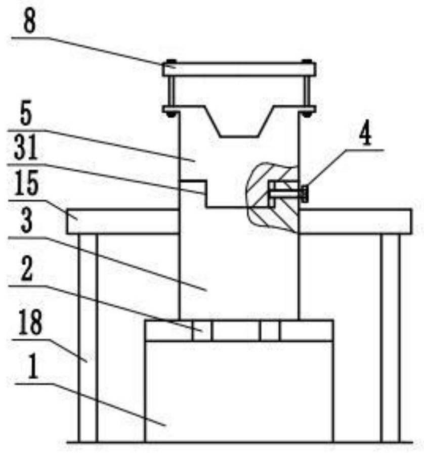
[0039] The clamping unit includes a fixed support seat 3 and a dynamic support seat 5, and also includes a pressing plate 8 and several positioning bolts 4. The dynamic support seat 5 is detachably connected to the upper end of the fixed support seat 3 through several positioning bolts 4, and the dynamic support seat 5 and The fixed support seat 3 is positioned by the positioning surface 31, the height from the top surface of the movable support seat 5 to the upper surface of the total base 1 is equal to the height from the middle support 10 to the upper surface of the total base 1, and the fixed support seat 3 on one side passes through the electric slide rail-2 Sliding on the total base 1, the fixed support base 3 on the other side slides on the total base 1 through the electric slide rail 430, and the pressing plate 8 is detachably arranged on the top of the movable support base 5 through the bolt 7 and the nut 6. The top surface of the support seat 3 is a V-shaped surface. ...
PUM
 Abstract
Description
Claims
Application Information