Robot calibration system, two-dimensional plane motion calibration method and three-dimensional space motion calibration method

A technology for calibrating systems and robots, applied in the field of robotics

Active Publication Date: 2020-10-20
TONGJI UNIV
View PDF10 Cites 18 Cited by
  • Summary
  • Abstract
  • Description
  • Claims
  • Application Information

AI Technical Summary

Problems solved by technology

[0010] The purpose of the present invention is to provide a robot calibration system and a two-dimensional plane and three-dimensional space motion calibration method in order to overcome the defect that the robot cannot be calibrated online and in real time in the prior art

Method used


Image

  • Robot calibration system, two-dimensional plane motion calibration method and three-dimensional space motion calibration method
  • Robot calibration system, two-dimensional plane motion calibration method and three-dimensional space motion calibration method
  • Robot calibration system, two-dimensional plane motion calibration method and three-dimensional space motion calibration method

Examples


Embodiment

[0190] In this embodiment, taking the prism assembly 31 as a double prism as an example, the two-dimensional plane motion calibration method of the system is as follows:

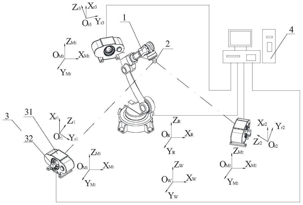
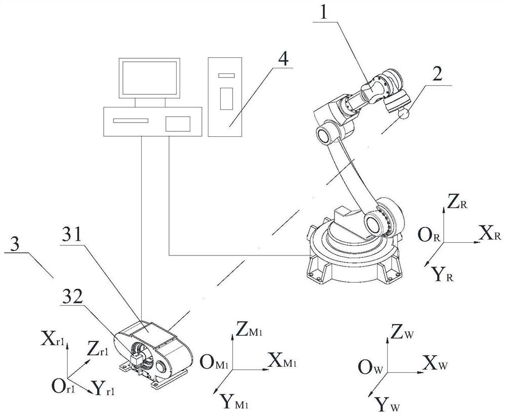
[0191] a1. Establish the world coordinate system O w -X w Y w Z w , establish the robot coordinate system O R -X R Y R Z R , establish the measurement component coordinate system O M -X M Y M Z M , establish the coordinate system O of the prism component in the measurement component 3 r -X r Y r Z r , set up the camera coordinate system O matched with the prism assembly 31 c -X c Y c Z c , will measure the component coordinate system O M -X M Y M Z M , the world coordinate system O w -X w Y w Z w And the camera coordinate system O matched with the measurement component 3 c -X c Y c Z c ;

[0192] a2. The host computer 4 controls the prism assembly 31 of the measurement assembly 3, so that the visual axis of the camera 32 passes through the prism assembly 31 without deflection, a...


PUM


Abstract

The invention relates to a robot calibration system, a two-dimensional plane motion calibration method and a three-dimensional space motion calibration method. The system comprises an industrial robotand an upper computer, and further comprises a target, measuring assemblies and a calibration assembly. The target is fixedly installed at the tail end of the industrial robot. The measuring assemblies are arranged on the periphery of the industrial robot, and each measuring assembly comprises a prism assembly and a camera. The prism assemblies are arranged between the target and the cameras, andthe visual axis of each camera and the optical axis of the corresponding prism assembly are kept coaxial. The calibration assembly is arranged in the view field of the measuring assemblies and does not interfere with the industrial robot. The upper computer is connected with the cameras and the prism assemblies. Compared with the prior art, the robot calibration system has the advantages that theupper computer can control the prism assemblies and adjust the visual axes of the cameras matched with the prism assemblies, the real-time dynamic measurement of the center position of the target isachieved, an error response equation of nominal coordinates and measurement coordinates of current geometrical parameters of the robot is constructed, the corresponding current geometrical parametersof the robot in the process that the error is minimum are sought, and the online calibration of the robot can be achieved.

Description

technical field [0001] The invention relates to the technical field of robots, in particular to a robot calibration system and a two-dimensional plane and three-dimensional space motion calibration method. Background technique [0002] With the introduction of a new round of scientific and technological revolution, the continuous development of intelligent factories, intelligent workshops and intelligent production lines, industrial robots have the characteristics of flexibility, repeatability and strong load capacity, and have been widely used in welding, automobile assembly and aerospace manufacturing. And handling and palletizing and other fields, and the working precision of industrial robots at this stage is difficult to meet the increasingly high requirements of processing and manufacturing precision. The errors of industrial robots mainly include kinematic errors such as rod error and joint angle error, as well as non-geometric errors such as environmental temperature...

Claims


Application Information

Patent Timeline
Patent Type & Authority Applications(China)
IPC IPC(8): B25J9/16
CPCB25J9/1653
Inventor 李安虎
Owner TONGJI UNIV
Why Eureka
Try Eureka