Safety retracement method for combined coal and oil shale mining

A combined mining and oil shale technology, applied in safety devices, ground mining, mining devices, etc., can solve problems such as high temperature, long withdrawal period, and inability to ensure withdrawal safety

Inactive Publication Date: 2020-10-20
LONGKOU MINING GRP
View PDF0 Cites 1 Cited by
  • Summary
  • Abstract
  • Description
  • Claims
  • Application Information

AI Technical Summary

Problems solved by technology

[0006] The purpose of the present invention is to provide a method for safe withdrawal of coal and oil shale joint mining, to solve the existing conventional fire prevention measures proposed in the above background technology is to control the air volume of the working face, Drilling and grouting the coal body in front of the roof are mainly used to reduce air leakage channels and control natural ignition. Due to the parallel operation of drilling grouting in front and retraction of the working face, the removal period is long, the coal body is prone to spontaneous combustion, and high temperature phenomenon occurs. The effect is good. Poor, unable to ensure safe withdrawal

Method used


Image

  • Safety retracement method for combined coal and oil shale mining
  • Safety retracement method for combined coal and oil shale mining

Examples


Embodiment 1

[0048] A safety retraction method for joint mining of coal and oil shale, comprising the following steps:

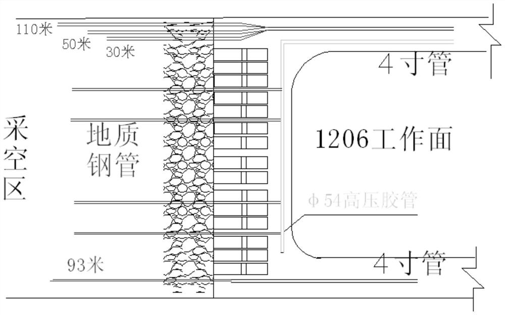
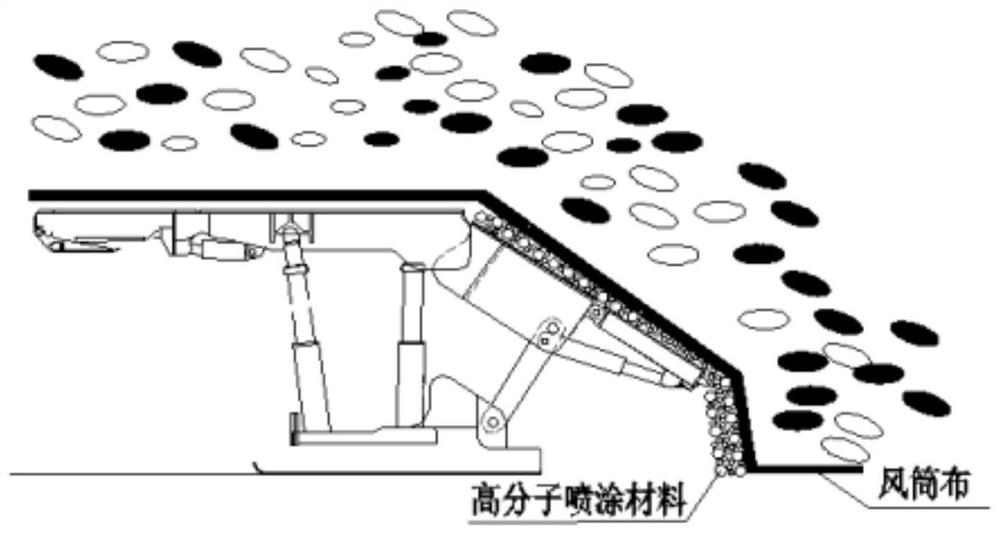
[0049] S1: Gas monitoring: Before laying the net rope, the key positions such as the inlet and return corners of the working face, and the crusher of the transportation lane are respectively installed to remove CO 2 , CO, O 2 Temperature and other probes, and use the bundle pipe buried in the corner of the return air to take gas samples for analysis every day, install a normally open water curtain at the two corners of the working face, and every 25 bracket nests on the working face, spray to the back of the frame Goaf, and keep it in the normal open state, disturb the gas and reduce the temperature of the goaf behind the rack;

[0050] Before partial ventilation of the working face, install a CO and a CO respectively at the front of the chassis 2 , O 2 、CH 4 Probes; install a CO at a position 3 meters outward from the large curve 2、 CO, CH 4 Probes; one O is insta...

Embodiment 2

[0068] A safety retraction method for joint mining of coal and oil shale, comprising the following steps:

[0069] S1: Gas monitoring: Before laying the net rope, the key positions such as the inlet and return corners of the working face, and the crusher of the transportation lane are respectively installed to remove CO 2 , CO, O 2 Temperature and other probes, and use the bundle pipe buried in the corner of the return air to take gas samples for analysis every day, install a normally open water curtain at the two corners of the working face, and every 30 bracket nests on the working face, spray to the back of the frame Goaf, and keep it in the normal open state, disturb the gas and reduce the temperature of the goaf behind the rack;

[0070] Before partial ventilation of the working face, install a CO and a CO respectively at the front of the chassis 2 , O 2 、CH 4 Probes; install a CO at a position 3 to 5 meters outward from the large curve 2、 CO, CH 4 Probes; one O is ...


PUM


Abstract

The invention belongs to the technical field of mining safety retracement methods, and specifically discloses a safety retracement method for combined coal and oil shale mining. The method comprises the following step of S1, gas monitoring before laying the rope on the net. The safety retracement method for combined coal and oil shale mining controls the mining layer of a working face, prevents coal from entering a goaf, reduces the combustible content of the goaf, uses the working face again to lay air duct cloth above the support of the working face during the tailing of the working face, seals both corners of the working face to reduce air leakage in the goaf, and finally uses pipelines laid in advance to multiple locations in the goaf to inject inert gas and grouting to seal the goaf and reduce the temperature in the goaf, thereby fundamentally weakening or eliminating the basic conditions required for spontaneous combustion of coal, so as to reduce the safety pressure for fire prevention and achieve safe retracement.

Description

technical field [0001] The invention relates to the technical field of mining safety withdrawal methods, in particular to a safety withdrawal method for joint mining of coal and oil shale. Background technique [0002] Coal mines are areas where human beings exploit coal resources in coal-rich mining areas. They are generally divided into underground coal mines and open-pit coal mines. When the distance to the surface is very short, it is generally chosen to directly strip the surface soil layer to excavate coal, which is an open-pit coal mine. [0003] In the mining mode, there will be a joint mining arrangement of coal and oil shale, and because the coal seam below has been mined, it is a typical upward mining. This mining mode has a great risk of easily causing the recovery of the working face to end and the mining during the withdrawal period. Empty areas naturally get angry, which brings hidden dangers to safe production. [0004] Since the working face belongs to the...

Claims


Application Information

Patent Timeline
Patent Type & Authority Applications(China)
IPC IPC(8): E21C41/18E21F1/00E21F5/04E21F5/08E21F17/18
CPCE21C41/18E21F1/006E21F5/04E21F5/08E21F17/18
Inventor 任尧喜刘攀龙徐立茂刘明明王洋
Owner LONGKOU MINING GRP
Why Eureka
Try Eureka