
Compressor oil pumping structure, compressor and refrigeration equipment

A compressor pump and connecting structure technology, applied in the field of compressors, can solve the problems of oil suction pipe rebound, loosening, falling off, stuck and other problems

Active Publication Date: 2020-10-20
WANBAO GROUP COMPRESSOR CO LTD
View PDF8 Cites 0 Cited by
  • Summary
  • Abstract
  • Description
  • Claims
  • Application Information

AI Technical Summary

Problems solved by technology

The two methods are interference fit to assemble the oil suction pipe parts. In the first method, the oil suction pipe is squeezed into the first-stage oil inlet hole in a way that the diameter becomes smaller. The oil suction pipe cannot rebound or loosen, so the assembly is tight and the connection is reliable. , while in method 2, the oil suction pipe is set on the outer surface of the crankshaft in a way that the diameter becomes larger. The compressor works for a long time. After long-term vibration, repeated heating and cooling, the oil suction pipe will rebound and loosen, resulting in The components rotate relative to the crankshaft or even fall off, the oil pump fails to work, the compressor loses its ability to pump oil, the moving parts cannot be lubricated, and the friction pairs are worn and stuck, causing the compressor to be scrapped

Method used


Image

  • Compressor oil pumping structure, compressor and refrigeration equipment
  • Compressor oil pumping structure, compressor and refrigeration equipment
  • Compressor oil pumping structure, compressor and refrigeration equipment

Examples


Embodiment Construction

[0030] This part will describe the specific embodiment of the present invention in detail, and the preferred embodiment of the present invention is shown in the accompanying drawings. Each technical feature and overall technical solution of the invention, but it should not be understood as a limitation on the protection scope of the present invention.

[0031] In the present invention, if there is a description of directions (up, down, left, right, front and back), it is only for the convenience of describing the technical solution of the present invention, rather than indicating or implying that the referred technical features must have specific Orientation, construction and operation in a particular orientation, therefore should not be construed as limiting the invention.

[0032] In the present invention, "several" means one or more, "multiple" means more than two, "greater than", "less than", "exceeding", etc. are understood as excluding the original number; "above", "belo...


PUM


Abstract

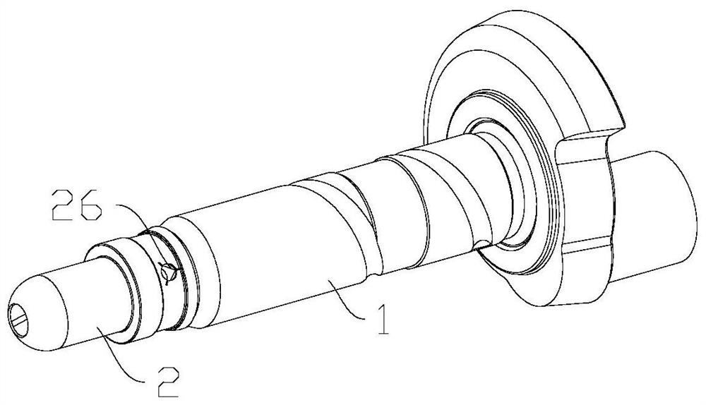
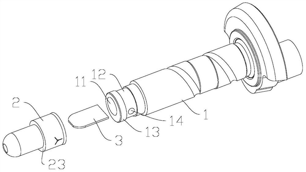
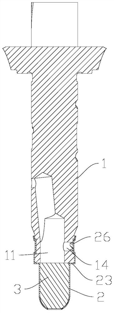
The invention discloses a compressor oil pumping structure, a compressor and refrigeration equipment. The structure comprises a crankshaft, an oil inlet hole is formed in the tail part of the crankshaft; the oil inlet hole is deviated relative to the axis of the crankshaft; a clamping groove is formed in the peripheral surface of the tail of the crankshaft, a clamping boss is formed between the clamping groove and the end face of the tail of the crankshaft, an exhaust through hole is formed in the clamping boss and / or the clamping groove, the exhaust through hole communicates with the oil inlet hole, and the exhaust through hole is located in the side, opposite to the offset direction of the oil inlet hole, of the crankshaft. The structure also comprises an oil suction pipe which is connected to the tail of the crankshaft in a sleeving mode, the oil suction pipe shrinks in the radial direction and is pressed in the clamping groove of the crankshaft, and a clamping structure clamped inthe exhaust through hole is arranged on the oil suction pipe. The structure is simple, the oil suction pipe is reliable in installation and connection and cannot fall off, and relative rotating motioncannot occur; the inner diameter of the oil suction pipe can be maximized. Therefore, the compressor can obtain the maximum oil pumping capacity, the friction pair is safe and reliable, and the service life of the compressor is well guaranteed.

Description

technical field [0001] The invention is used in the field of compressors, and in particular relates to a compressor oil pumping structure, a compressor and refrigeration equipment. Background technique [0002] When the refrigeration compressor is working, the moving parts rotate at a high speed. In order to ensure the life and sealing performance of the moving parts, the friction pair needs to be lubricated sufficiently. Therefore, there is an oil pump in the compressor, which is driven by the high-speed rotating crankshaft to generate a large enough centrifugal force, the so-called lift, to raise the lubricating oil in the oil pool of the lower shell of the compressor and transport it to the various parts of the compressor core. In the friction pair of moving parts, it plays the functions of lubrication and sealing. The head of the oil pump is related to the inner diameter and speed of the oil pump. The larger the inner diameter, the larger the head, and the higher the sp...

Claims


Application Information

Patent Timeline
Patent Type & Authority Applications(China)
IPC IPC(8): F04C29/02F04C29/00
CPCF04C29/02F04C29/00F04C2240/601
Inventor 陈会平李顺吴丽华黄炳喜
Owner WANBAO GROUP COMPRESSOR CO LTD
Learn More