A detachable lighting tube with convenient fastening connection

A technology for convenient fastening and lighting, applied in lighting devices, lighting auxiliary devices, lighting and heating equipment, etc., can solve problems such as leakage, poor contact, easy to get hot, etc., to achieve reliable installation and connection, reduce leakage risks, The effect of improving the service life

Active Publication Date: 2022-04-05
江苏烨明光电有限公司
View PDF5 Cites 0 Cited by
  • Summary
  • Abstract
  • Description
  • Claims
  • Application Information

AI Technical Summary

Problems solved by technology

[0004] Therefore, the technical problem to be solved by the present invention is that the two ends of the traditional lamp tube are connected with electric wires, which tend to get hot after long-term use, and are prone to poor contact during installation, which will also cause the risk of electric leakage

Method used


Image

  • A detachable lighting tube with convenient fastening connection
  • A detachable lighting tube with convenient fastening connection
  • A detachable lighting tube with convenient fastening connection

Examples


Embodiment 1

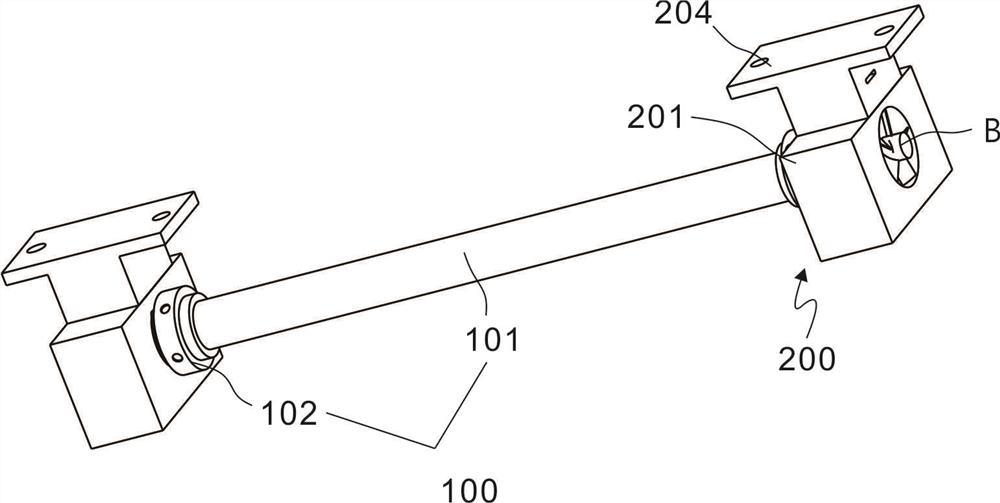
[0023] refer to Figure 1~Figure 4 , is the first embodiment of the present invention, which provides a detachable lighting tube for convenient fastening connection, including a lighting assembly 100 and a fastening assembly 200, and the fastening assembly 200 is arranged at both ends of the lighting assembly 100 , on the one hand for connecting the lighting assembly 100, on the other hand it can be installed on the ceiling.

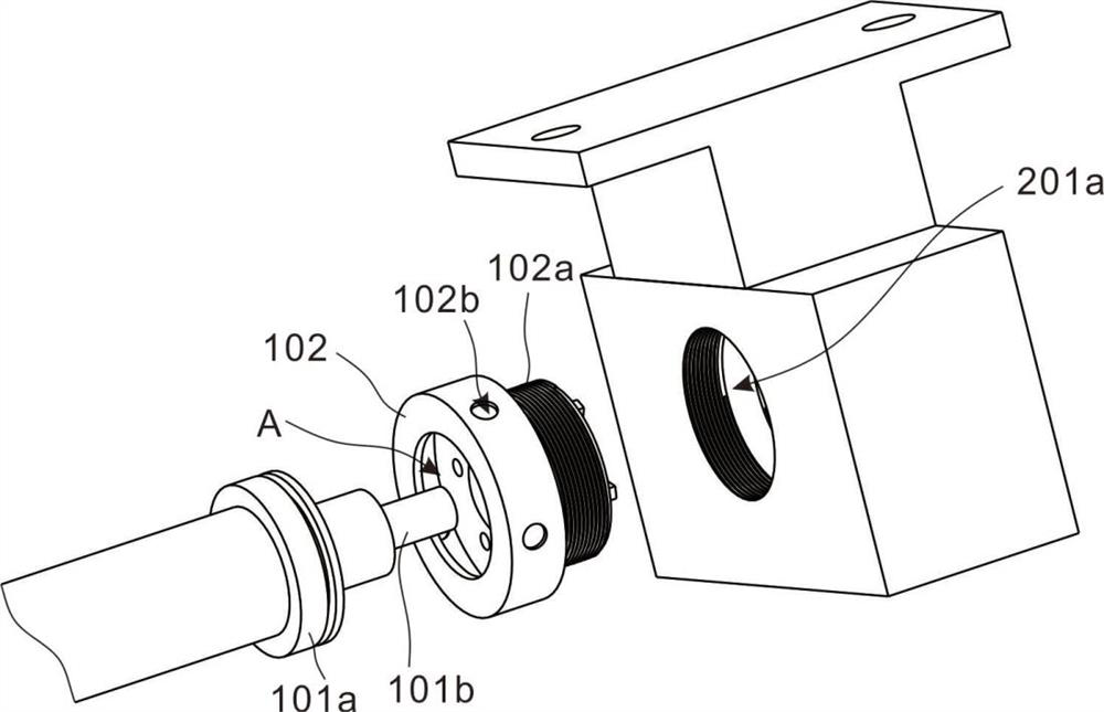
[0024] The lighting assembly 100 includes a lamp tube 101 and a connecting cover 102. Terminals 101a are provided at both ends of the lamp tube 101, and conductive heads 101b are vertically provided on the terminals 101a. The conductive head 101b is used to connect the power line, and the connecting cover 102 is connected to the terminal 101a in rotation; the connecting cover 102 has a circular outline and is hollow inside, and one side has a circular opening. Specifically, both ends of the lamp tube 101 are Through the connection cover 102, one end of ...

Embodiment 2

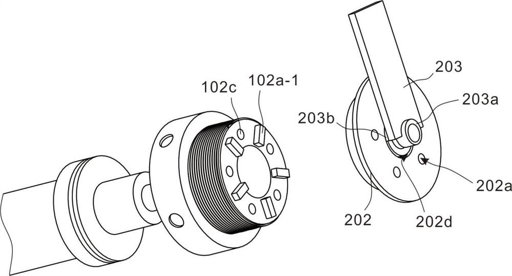
[0032] refer to Figure 1~Figure 4 , which is the second embodiment of the present invention. This embodiment is based on the previous embodiment. A block 102a-1 is provided on the side of the threaded pipe 102a facing the barrier sleeve 202, and a square groove 202c is provided on the side of the barrier sleeve 202 facing the threaded pipe 102a. The square 102a-1 is connected with the square groove 202c correspondingly; when the lamp tube 101 is connected, the square 102a-1 is inserted into the square groove 202c so that the threaded pipe 102a and the barrier sleeve 202 are connected together, and the two can rotate synchronously to ensure a tight connection, or It is ensured that the third round hole 202a corresponds to the second round hole 102c.

[0033] The fastening assembly 200 further includes a conductive sheet 203, and an opening 201b is disposed on the top of the lamp holder 201, and the opening 201b communicates with the cavity 201a. One end of the conductive shee...


PUM


Abstract

The invention discloses a detachable lighting lamp tube which is conveniently fastened and connected, which comprises a lighting assembly, the lighting assembly includes a lamp tube and a connecting cover, terminals are arranged at both ends of the lamp tube, and conductive heads are vertically arranged on the terminals , the connecting cover is sleeved on both ends of the lamp tube, the connecting cover is embedded on the outer wall of the terminal and connected to the terminal in rotation; and a barrier sleeve, the lamp holder is provided with a cavity, the barrier sleeve is installed in the cavity, and the conductive head is inserted into the cavity through the connection cover and connected with the barrier sleeve; the present invention adds A fastening device is provided to match the lamp holder. The outer wall is made of insulating material, which makes the installation safer, avoids direct contact with the internal wires during installation, reduces the risk of leakage, and makes the installation and connection more reliable. It has the function of ventilation and heat dissipation, and reduces electrical conductivity The temperature of the wire can increase the service life.

Description

technical field [0001] The invention relates to the technical field of lamp tube fastening, in particular to a detachable lamp tube for fastening and connection. Background technique [0002] At present, fluorescent lamps on the market are divided into ordinary fluorescent lamps and LED fluorescent lamps. Ordinary fluorescent lamps are also called fluorescent lamps. They are thin and long. There is a filament at each end of the lamp tube. , the inner wall of the lamp tube is coated with phosphor powder, and the gas between the two filaments emits ultraviolet light when it conducts electricity, so that the phosphor powder emits soft visible light; the lamp tube of the LED fluorescent lamp uses argon-oxygen decarburized super bright LED white light as the light source. The shell is made of plexiglass or aluminum alloy. Contents of the invention [0003] The purpose of this section is to outline some aspects of embodiments of the invention and briefly describe some preferred...

Claims


Application Information

Patent Timeline
Patent Type & Authority Patents(China)
IPC IPC(8): F21S2/00F21V21/00F21V21/002F21V23/06F21V29/60F21V29/67F21Y103/00
CPCF21S2/00F21V21/00F21V23/06F21V21/002F21V29/60F21V29/67F21Y2103/00
Inventor 陈旭
Owner 江苏烨明光电有限公司
Why Eureka
Try Eureka