Installation structure for cooling fan of generator

A cooling fan and installation structure technology, which is applied in the direction of cooling/ventilation devices, electromechanical devices, machines/engines, etc., can solve the problems of non-common cooling fans, large differences in shaft diameters, waste, etc.

Inactive Publication Date: 2020-10-20
上海马拉松·革新电气有限公司
View PDF6 Cites 0 Cited by
  • Summary
  • Abstract
  • Description
  • Claims
  • Application Information

AI Technical Summary

Problems solved by technology

In the above two cases, whether it is human or material cost, it is a great waste
[0004] In addition, due to the difference in the output power of the generator, the diameter of the rotating shaft of the generator will also be d

Method used


Image

  • Installation structure for cooling fan of generator
  • Installation structure for cooling fan of generator
  • Installation structure for cooling fan of generator

Examples


Embodiment Construction

[0026] The present invention will be further described below in conjunction with accompanying drawing.

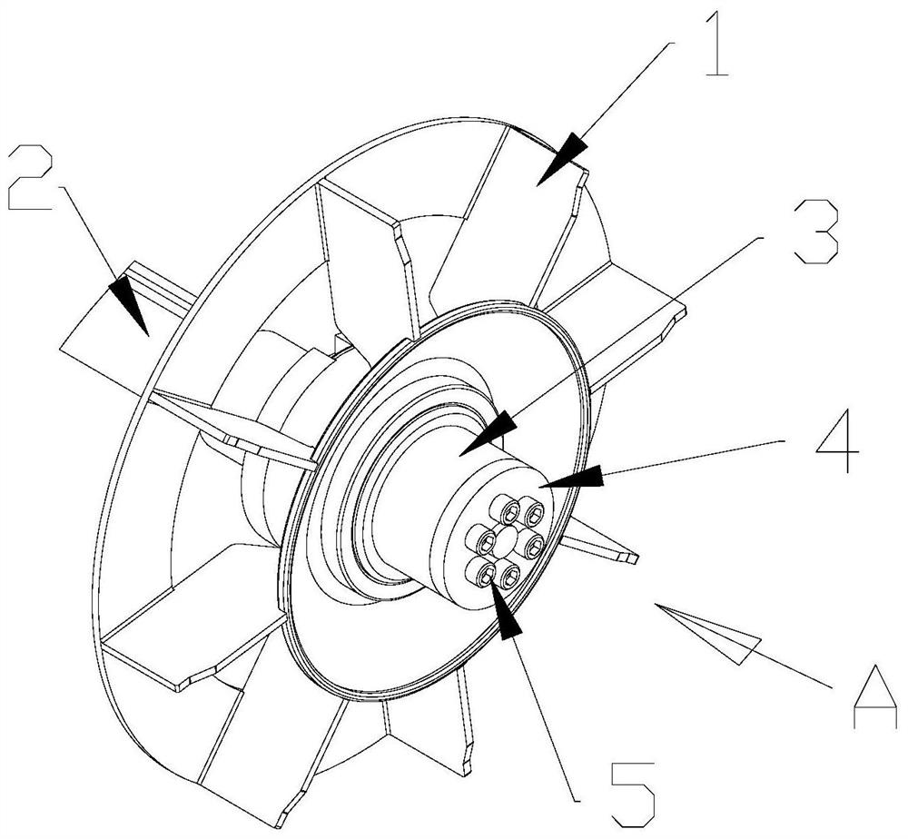
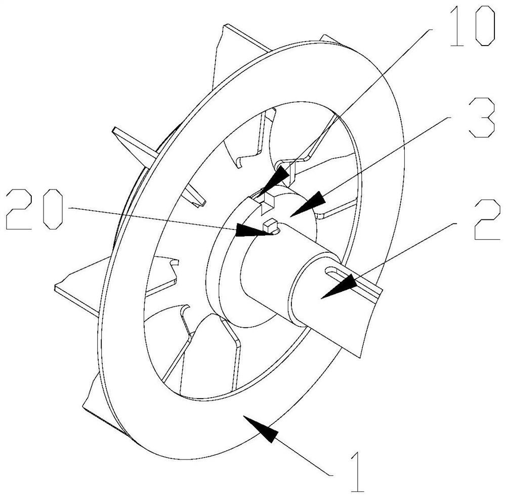
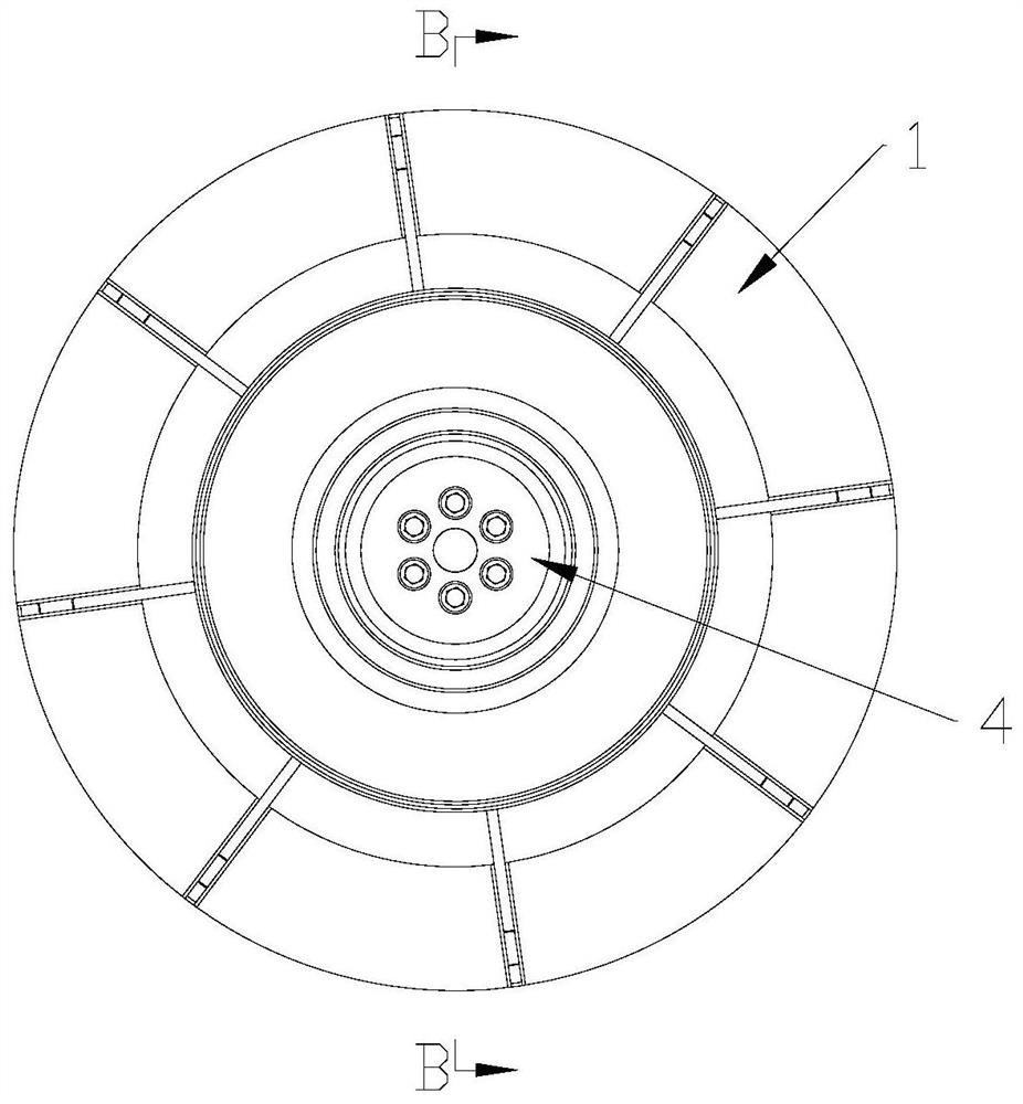
[0027] see Figure 1 to Figure 6 , the installation structure of the cooling fan of the generator of the present invention, including the generator shaft 2, the fan body 1, the central shaft sleeve 3 and the peripheral locking plate 4; wherein,

[0028] One end of the generator shaft 2 where the fan body 1 is installed is a two-step cylindrical section whose diameter becomes smaller from the inside to the outside, including the inner shaft section 21, the intermediate shaft section 22 and the outer shaft section 23; the outer shaft section 23 A cylindrical rotating shaft outer end 24 is also extended outward on the end face, and six threaded blind holes are evenly distributed axially on the outer end face of the outer rotating shaft section 23 on a circumference concentric with the generator rotating shaft 2; the inner rotating shaft A waist-shaped rotating shaft keyway 20...


PUM


Abstract

The invention discloses an installation structure for a cooling fan of a generator. The installation structure comprises a generator rotary shaft, a fan body, a center shaft sleeve and a peripheral lock plate. Firstly, the center shaft sleeve is inserted in a shaft hole of the fan body in a mode that a shaft sleeve groove is aligned with a fan boss on the fan, and thus the fan boss enters the shaft sleeve groove; then the center shaft sleeve with the fan body is installed on the generator rotary shaft in a sleeving mode, a shaft sleeve boss on the center shaft sleeve is embedded into a rotaryshaft key groove in the generator rotary shaft, the inner end face of the center shaft sleeve leans against the stepped face between the inner rotary shaft section and the middle rotary shaft sectionof the generator rotary shaft, and the outer end face of the center shaft sleeve is flush with the outer end face of the outer rotary shaft section; and then the peripheral lock plate is arranged on the outer end head of the rotary shaft in a sleeving mode, a plurality of installation holes in the peripheral lock plate are aligned with a plurality of threaded blind holes in the generator rotary shaft one by one, and then the peripheral lock plate is fixed to the generator rotary shaft through a plurality of bolts. The installation structure for the cooling fan has the characteristics of convenient installation, flexible replacement and disassembly and the like.

Description

technical field [0001] The invention relates to an installation structure of a cooling fan of a generator. Background technique [0002] The temperature rise assessment is an important indicator of generator performance. The temperature rise will directly affect the heat loss index of the generator and indirectly affect the efficiency of the generator. The cooling fan of the generator is the important and only active cooling part to control the temperature rise of the generator. If the cooling fan is faulty or defective, it must be adjusted and replaced immediately, otherwise the output and performance of the generator will be greatly affected, and even due to The internal heat dissipation of the generator is not smooth, causing damage to the generator as a whole. In order to obtain the maximum heat dissipation effect, the cooling fan is often the part with the largest outer diameter in the rotor structure of the generator. Due to the large starting torque of the generator ...

Claims


Application Information

Patent Timeline
IPC IPC(8): F04D25/08F04D29/00F04D29/054F04D29/62H02K9/06
CPCF04D25/08F04D29/002F04D29/054F04D29/626H02K9/06
Inventor 迟睿新张燕周伟强
Owner 上海马拉松·革新电气有限公司
Why Eureka
Try Eureka