Construction method and device of visual point cloud map

A construction method and map technology, applied in the field of navigation and positioning

Active Publication Date: 2020-10-20
HANGZHOU HIKROBOT TECH CO LTD
View PDF8 Cites 10 Cited by
  • Summary
  • Abstract
  • Description
  • Claims
  • Application Information

AI Technical Summary

Problems solved by technology

In terms of input, before the robot runs, there is no special input. When it starts running, there are sensor raw data. In terms of output, the estimated pose and estimated map; that is, when building a new map model or improving a known map At the same time, positioning the robot on the map

Method used


Image

  • Construction method and device of visual point cloud map
  • Construction method and device of visual point cloud map
  • Construction method and device of visual point cloud map

Examples


Embodiment 1

[0036] For ease of understanding, in this embodiment, the image data is collected by a monocular camera and the image is ground texture as an example for illustration. It should be understood that this embodiment is not limited to ground texture images, and other images are also applicable.

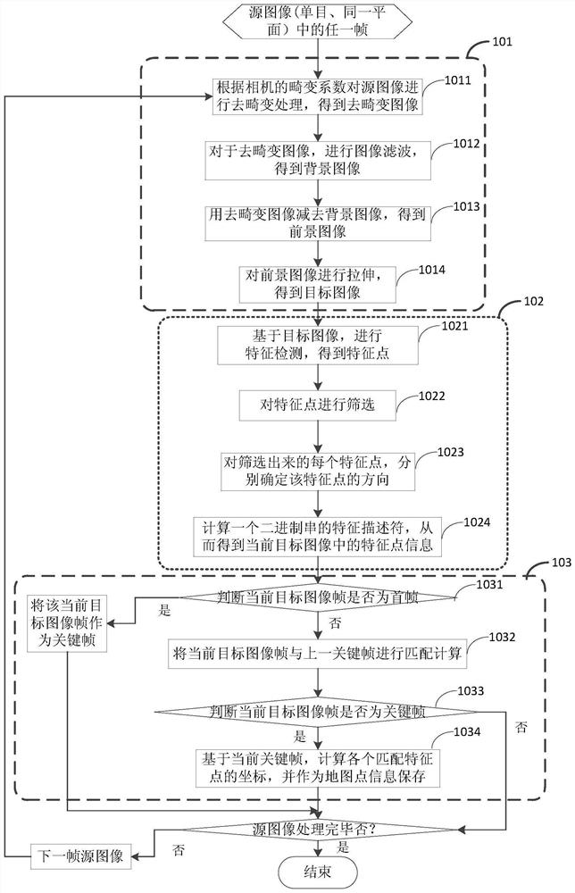
[0037] see figure 1 as shown, figure 1 Schematic diagram of a process for building a map based on image data collected by a monocular camera. It mainly includes image preprocessing, feature extraction, and inter-frame tracking. Specifically, for each frame of source image, the following steps are performed:

[0038] Step 101, using the collected image as the source image, preprocessing the image to obtain the target image, so as to extract the feature points in the image, for example, for the ground texture image, the purpose of the preprocessing is to obtain the texture information main image.

[0039] Step 1011, perform de-distortion processing on the source image according to the d...

Embodiment 2

[0091] In this embodiment, the image data is collected by a monocular camera, and the collected images are not on the same plane as an example for illustration. For example, the camera is mounted forward-looking, that is, the mobile robot collects images through the forward-looking camera.

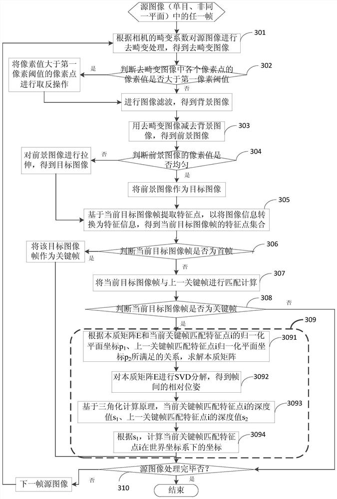
[0092] see image 3 as shown, image 3 Schematic diagram of a process for building a map based on forward-looking image data collected by a monocular camera. For each frame of image, perform the following steps:

[0093] In step 301, the source image is de-distorted according to the distortion coefficient of the camera to obtain a de-distorted image I(u, v), where u and v represent pixel coordinates.

[0094] Step 302, judging whether the pixel value of each pixel in the de-distorted image is greater than the set first pixel threshold, if so, performing an inversion operation on the pixel whose pixel value is greater than the first pixel threshold, and then inverting Filter the de-dist...

Embodiment 3

[0133] In this embodiment, it is illustrated by taking image data collected by binocular cameras as an example, and the collected images are not on the same plane.

[0134] see Figure 4 as shown, Figure 4 Schematic diagram of a process for building a map based on image data collected by a binocular camera. For each binocular image frame, that is, at the same time from the first source image frame of the first purpose and from the second source image frame of the second purpose, the following steps are performed:

[0135] Step 401, performing image preprocessing on the first source image frame and the second source image frame to obtain the current binocular target image frame, including the first target image frame and the second target image frame;

[0136] In this step, image preprocessing may be performed on the first image frame and the second image frame in parallel, or image preprocessing may be performed serially on the first image frame and the second image frame r...


PUM


Abstract

The invention discloses a construction method of a visual point cloud map. The method includes the steps of: carrying out feature extraction on an acquired source image frame of the space of the to-be-built map; obtaining a source image frame feature point; performing inter-frame tracking on the source image frame; determining key frames, matching the feature points in the current key frame with the feature points in the previous key frame; obtaining matching feature points of the current key frame, calculating spatial position information of the matching feature points in the current key frame, taking the spatial position information of the matching feature points as map point information of the current key frame, and taking point cloud formed by map point sets of all key frames as a first visual point cloud map. According to the method, mapping and positioning are separated in the map construction process, the mutual influence of mapping and positioning is effectively removed, and the method has better adaptability and stability in a complex and changeable environment.

Description

technical field [0001] The invention relates to the field of navigation and positioning, in particular, to a method for constructing a visual point cloud map. Background technique [0002] Map construction and positioning are the key technologies in the research of real-time location and map (SLAM), and map construction is the prerequisite for positioning. The quality of the map directly affects the accuracy of positioning. The visual point cloud map is one of the constructed maps. It describes the vision, pose and other information of points in the environment through the three-dimensional point set in space. Therefore, two types of data information are required to construct a visual point cloud map: the key Frames and map points, where the key frame describes the vision of the point in the environment, the map point describes the pose of the point, and the collection formed by a large number of map points constitutes a point cloud. [0003] SLAM is to start the robot from...

Claims


Application Information

Patent Timeline
IPC IPC(8): G01C21/32G06K9/62G06K9/32G06K9/00G06F16/29
CPCG01C21/32G06F16/29G06V20/46G06V20/62G06F18/22
Inventor 易雨亭李建禹龙学雄党志强
Owner HANGZHOU HIKROBOT TECH CO LTD
Why Eureka
Try Eureka