
Microstructure lens array and space positioning method based on microstructure lens array

A lens array and microstructure technology, applied in the field of optics, can solve the problems of conventional lens arrays such as low precision, large lens size, unfavorable positioning system miniaturization, etc.

Active Publication Date: 2020-10-20
NANKAI UNIV
View PDF6 Cites 0 Cited by
  • Summary
  • Abstract
  • Description
  • Claims
  • Application Information

AI Technical Summary

Problems solved by technology

[0002] The conventional lens array used in the prior art for positioning has the following disadvantages: 1. The conventional lens is large in size, which is not conducive to the miniaturization of the positioning system; 2. The positioning accuracy of the conventional lens array is low

Method used


Image

  • Microstructure lens array and space positioning method based on microstructure lens array
  • Microstructure lens array and space positioning method based on microstructure lens array
  • Microstructure lens array and space positioning method based on microstructure lens array

Examples


Embodiment 1

[0023] An embodiment of the present invention provides a microstructure lens array. The microstructure lens array includes at least two microstructure lenses. The microstructure lens includes a plurality of prism cells. The prism cells include a silicon dioxide substrate and The titanium oxide prisms on the substrate include: a plurality of prism cells are arranged periodically.

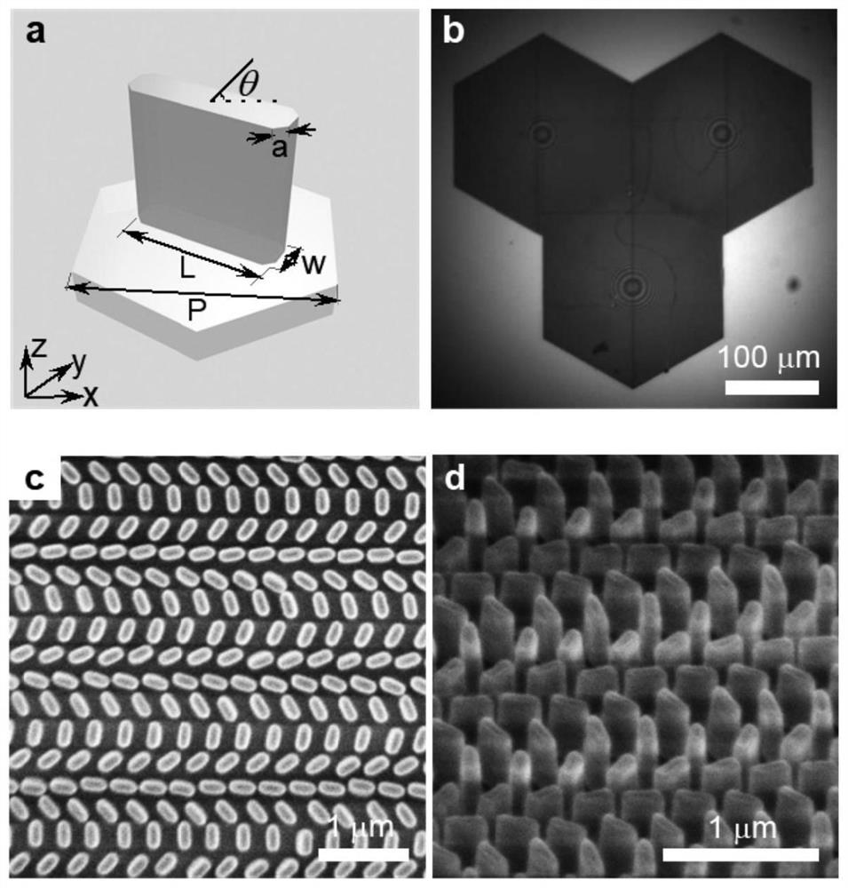
[0024] Optionally, figure 1 is a structural schematic diagram of a microstructure lens array provided according to an embodiment of the present invention, wherein, figure 1 Figure a in the figure is a schematic diagram of the structure of the prism cell of the microstructure lens array. Such as figure 1 As shown in Figure a, the titanium oxide prisms are titanium oxide octagonal prisms, and the silicon dioxide substrate is a regular hexagonal structure.

[0025] Specifically, as figure 1 As shown in Figure a, the titanium oxide prism is obtained by cutting four ribs in the z direction (cutting le...

Embodiment 2

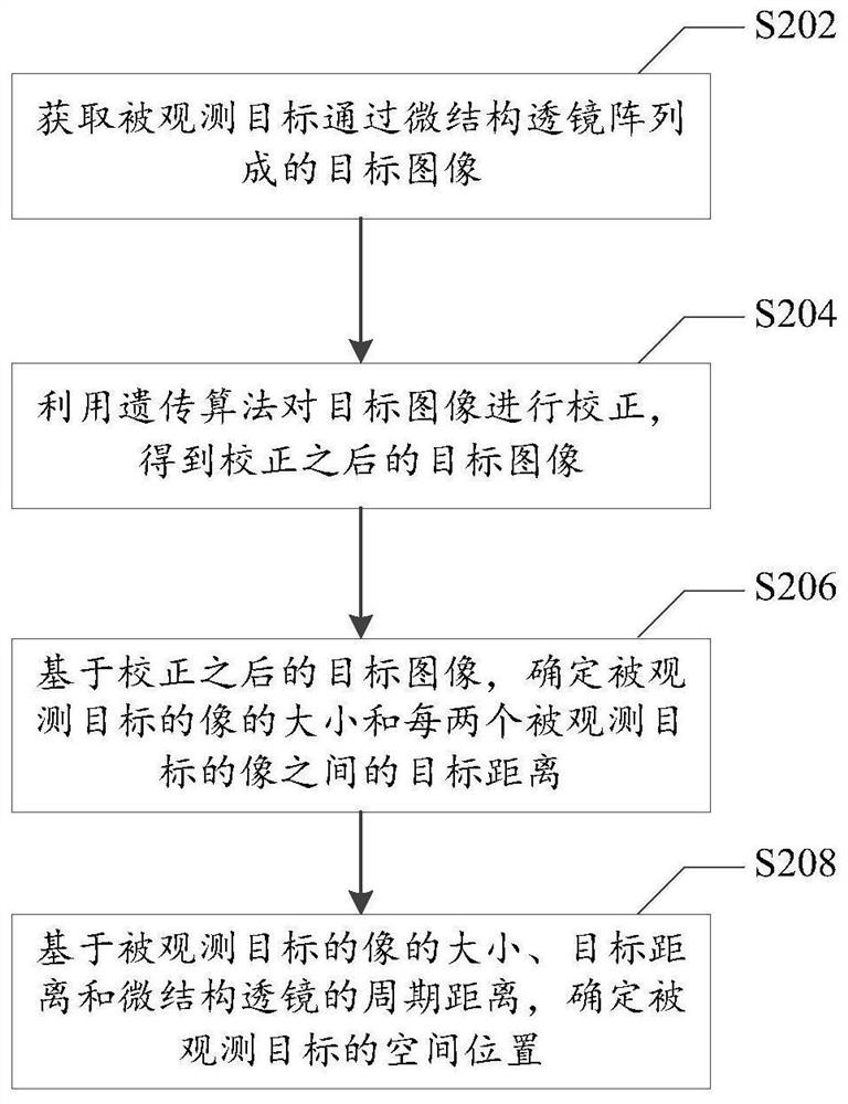
[0031] figure 2 It is a flow chart of a spatial positioning method based on a microstructure lens array according to an embodiment of the present invention, and the method is applied to the microstructure lens array in the first embodiment above. Such as figure 2 As shown, the method specifically includes the following steps:

[0032] Step S202, acquiring the target image formed by the micro-structured lens array of the observed target; the target image includes multiple images of the observed target, and one micro-structured lens corresponds to one image of the observed target. For example, if the micro-lens array includes three micro-lenses, the object image includes images of three observed objects.

[0033] Step S204, using the genetic algorithm to correct the target image to obtain the corrected target image; wherein, the variables to be optimized by the genetic algorithm include: the scaling amount of the target image in the horizontal direction, the translation amou...


PUM


Abstract

The invention provides a microstructure lens array and a space positioning method based on the microstructure lens array. The microstructure lens array comprises at least two microstructure lenses, each microstructure lens comprises a plurality of prism cells, each prism cell comprises a silicon dioxide substrate and a titanium oxide prism placed on the silicon dioxide substrate, and the pluralityof prism cells are periodically arranged. The technical problems that in the prior art, a lens is large in size and low in positioning precision are solved.

Description

technical field [0001] The invention relates to the field of optical technology, in particular to a microstructure lens array and a spatial positioning method based on the microstructure lens array. Background technique [0002] The conventional lens array used in the prior art for positioning has the following disadvantages: 1. The conventional lens is large in size, which is not conducive to the miniaturization of the positioning system; 2. The positioning accuracy of the conventional lens array is low. Contents of the invention [0003] In view of this, the object of the present invention is to provide a microstructure lens array and a space positioning method based on the microstructure lens array, so as to alleviate the technical problems of large lens volume and low positioning accuracy in the prior art. [0004] In the first aspect, an embodiment of the present invention provides a microstructure lens array, the microstructure lens array includes at least two micros...

Claims


Application Information

Patent Timeline
Patent Type & Authority Applications(China)
IPC IPC(8): G02B3/00G06N3/12
CPCG02B3/0037G06N3/126G02B1/002G02B3/0056G02B27/0025G02B3/0006
Inventor 陈树琪刘文玮玛地娜程化田建国
Owner NANKAI UNIV
Learn More