Motor rotor and end ring casting equipment and method thereof
A technology for motor rotors and casting equipment, applied in mechanical equipment, rotors, manufacturing squirrel cage rotors, etc., can solve problems such as poor fusion of copper raw materials, poor quality, and increased equipment costs
- Summary
- Abstract
- Description
- Claims
- Application Information
AI Technical Summary
Problems solved by technology
Method used
Image

Examples
Embodiment 1
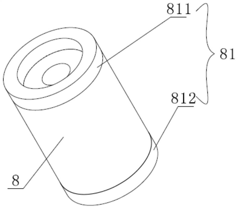
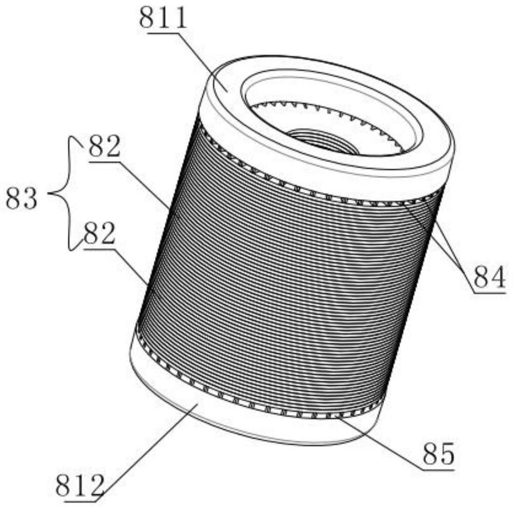
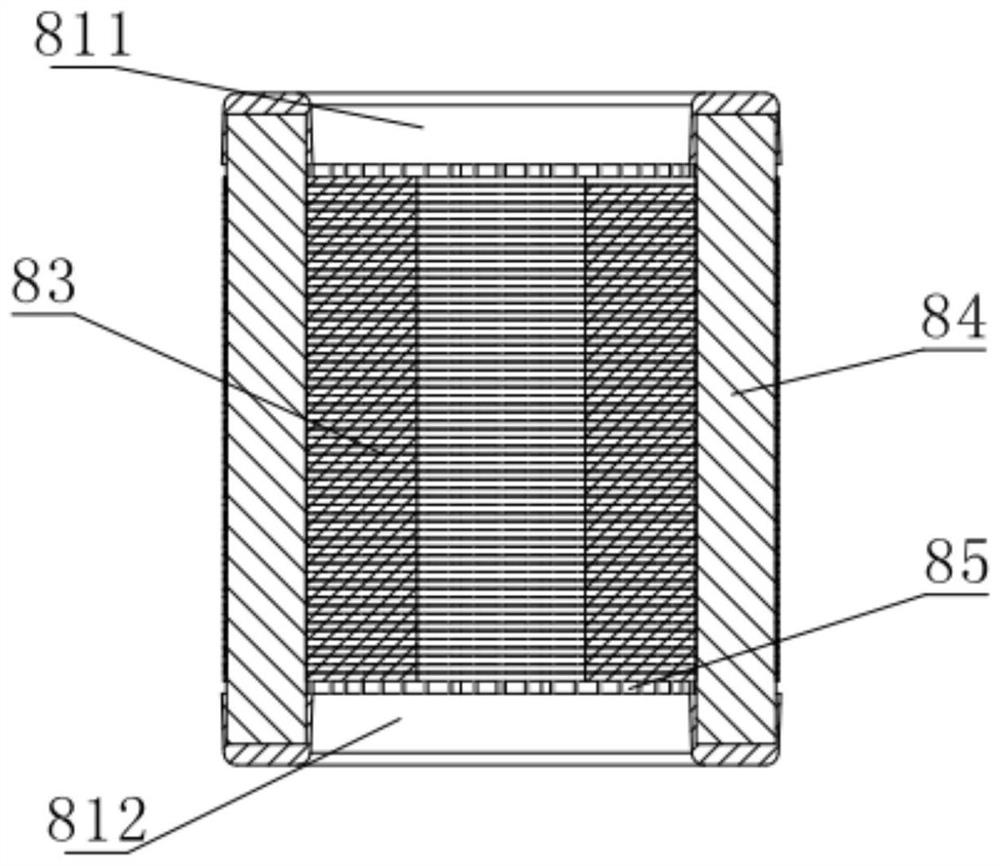
[0082] Such as Figure 1 to Figure 3 As shown, a motor rotor assembly includes an end ring 81 and a stack of laminations 83 , wherein the end ring 81 includes a first end ring 811 and a second end ring 812 . The motor rotor assembly includes a first end ring 811 , a stack of laminations 83 formed by stacking a plurality of lamination discs 82 and a second end ring 812 from top to bottom. The first end ring 811 , the stack of laminations 83 and the second end ring 812 form a cylindrical rotor. In certain cases, the cross-section of the rotor may be oval, elliptical, rectangular or any other shape. The motor is an asynchronous motor.
[0083] The lamination group 83 is stacked up and down along the central axis by a plurality of lamination discs 82, and each lamination disc 82 is also provided with a through hole for inserting the conductor bar; wherein the conductor bar is preferably a copper bar 84, and the copper bar 84 passes through it. It is arranged in the through hole...
Embodiment 2
[0125] In this embodiment, the same as in the first embodiment, the induction coil 4 is set outside the cover body 1. Considering the process of immersing the rotor core 8 into the molten metal raw material, there are many ways to make the relative displacement between the forming mold 3 and the rotor core 8 . Therefore, in this embodiment, the immersion process is realized by driving the displacement of the rotor core 8 .
[0126] The difference between this embodiment and Embodiment 1 is that the lifting device is installed on the upper part of the cover body 1; the worm wheel 71 worm 72 and the worm screw 72 lifter are fixed on the top cover 11, and the worm screw 72 extends from the top cover 11 into the cover body 1 internal. The mandrel 2 is inserted into the rotor core 8, so that the shoulder 21 in the middle of the mandrel 2 presses against the inner wall of the rotor core 8; both ends of the mandrel 2 can be screwed into nuts to press the rotor core 8 tightly. A press...
Embodiment 3
[0131] The inventors found that, in the above two embodiments, if the induction coil 4 is installed outside the cover body 1, when heating the metal raw material, it is necessary to provide a relatively large power to the induction coil 4 to meet the requirement. Therefore if Figure 16 and Figure 17 As shown, in this embodiment, the induction coil 4 is installed inside the cover body 1 to reduce energy consumption.
[0132] The difference between the second embodiment and the first embodiment lies in the structure of the cover body 1 and the installation position of the coil. The cover body 1 in this embodiment includes an upper shell 14 and a lower shell 15; the openings of the upper shell 14 and the lower shell 15 A flange 16 is formed at the place; the upper shell 14 and the lower shell 15 are fixed by passing bolts on the flange 16 . An observation window 17 is also provided on the upper case 14 . The forming state of the end ring 81 inside the cover body 1 can be eff...
PUM
| Property | Measurement | Unit |
|---|---|---|
| Width | aaaaa | aaaaa |
Abstract
Description
Claims
Application Information
 - R&D
- Intellectual Property
- Life Sciences
- Materials
- Tech Scout
- Unparalleled Data Quality
- Higher Quality Content
- 60% Fewer Hallucinations
Browse by: Latest US Patents, China's latest patents, Technical Efficacy Thesaurus, Application Domain, Technology Topic, Popular Technical Reports.
© 2025 PatSnap. All rights reserved.Legal|Privacy policy|Modern Slavery Act Transparency Statement|Sitemap|About US| Contact US: help@patsnap.com