Main loop arrangement structure of three-phase alternating-current motor driving system controller

A motor drive system, three-phase AC technology, applied in the direction of AC motor control, control system, output power conversion device, etc., can solve problems such as reducing the reliability of motor drive control and affecting the switching characteristics of power modules

Pending Publication Date: 2020-10-20
ZHENGHAI GRP CO LTD
View PDF0 Cites 0 Cited by
  • Summary
  • Abstract
  • Description
  • Claims
  • Application Information

AI Technical Summary

Problems solved by technology

[0009] In the main circuit, due to the stray inductance of the bolt area A and the area B on both sides, it seri...

Method used


Image

  • Main loop arrangement structure of three-phase alternating-current motor driving system controller
  • Main loop arrangement structure of three-phase alternating-current motor driving system controller
  • Main loop arrangement structure of three-phase alternating-current motor driving system controller

Examples


Embodiment Construction

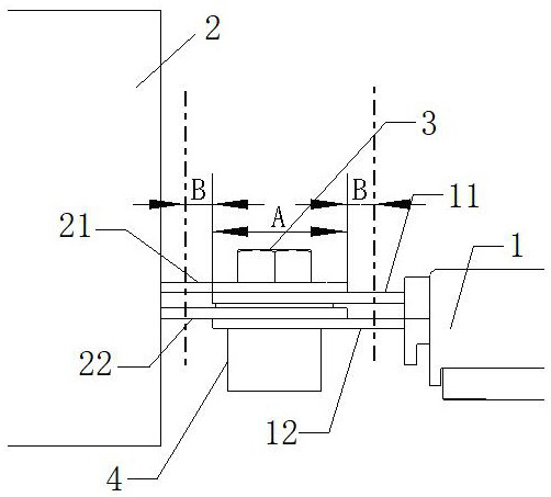
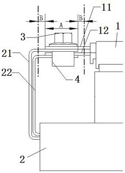
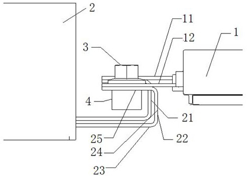
[0026] Example image 3 As shown, the main circuit layout structure of the three-phase AC motor drive system controller of the present invention includes a power module 1 with positive and negative busbars and a support capacitor 2 with positive and negative busbars, wherein the positive busbar 11 of the power module 1 The positive busbar 21 of the supporting capacitor 2 and the negative busbar 12 of the power module 1 and the negative busbar 22 of the supporting capacitor 2 are respectively connected with bolts 3 and inserts 4 to form an inverter main circuit. The positive and negative busbars of the power module 1 The busbars 11 and 12 extend along the installation plane to the position of the bolt 3 and the insert 4, the positive and negative busbars 21 and 22 of the support capacitor 2 extend horizontally in the direction of the power module 1 and then bend vertically to the positive and negative busbars. and then extend to the position of the bolt 3 and the insert 4 along...


PUM


Abstract

The invention discloses a main loop arrangement structure of a three-phase alternating-current motor driving system controller. The structure comprises a power module with positive and negative busbars and a support capacitor. The positive and negative busbars of the power module and the positive and negative busbars of the support capacitor are respectively connected by bolts and inserts to forman inversion main loop; positive and negative busbars of the power module extend to the positions of the bolts and the inserts along the mounting plane. The positive and negative busbars of the support capacitor horizontally extend towards the power module and then are vertically bent to the mounting plane; and the positive and negative busbars of the support capacitor extend to the positions of the bolts and the inserts along the mounting plane. The positive and negative busbars of the power module and the positive and negative busbars of the support capacitor are arranged in the same direction of the bolt and the insert, and the positive and negative busbars of the power module and the positive and negative busbars of the support capacitor are connected through the bolt and the insert respectively at the bolt and insert positions. According to the structure, surge voltage caused by stray inductance is reduced, the risk that the power module is broken down is avoided, the switching characteristic of the power module is ensured, and the reliability of motor driving control is improved.

Description

technical field [0001] The invention relates to the technical field of motor control, in particular to a main circuit layout structure of a three-phase AC motor drive system controller. Background technique [0002] In the three-phase AC motor drive system, the high-frequency carrier is used to drive the power module with high-speed switching tubes, and the surge voltage proportional to the stray inductance of the driving main circuit will be loaded on the power module. The surge voltage V 1 The calculation is as formula (1): [0003] [0004] in, [0005] but [0006] In the formula: L is the stray inductance, φ is the magnetic flux, I is the current, B is the magnetic induction intensity, a is the length of the main circuit connection terminal busbar, w is the main circuit connection terminal busbar width, and h is the spacing of the laminated busbars , μ 0 is the vacuum permeability. [0007] It can be seen that minimizing the stray inductance reduces the surg...

Claims


Application Information

Patent Timeline
IPC IPC(8): H02P25/16H02M7/00
CPCH02M7/003H02P25/16
Inventor 毛先叶张公明郭建文
Owner ZHENGHAI GRP CO LTD
Why Eureka
Try Eureka