Spot welding system

A technology of spot welding and welding head, applied in general control system, control/adjustment system, welding equipment, etc., can solve problems such as low efficiency of spot welding, cumbersome operation, and threat to personal safety of staff

Inactive Publication Date: 2020-10-23
GUIZHOU MINZU UNIV
View PDF7 Cites 1 Cited by
  • Summary
  • Abstract
  • Description
  • Claims
  • Application Information

AI Technical Summary

Problems solved by technology

[0003] With the development of electronic technology, electronic devices are becoming more and more miniaturized and integrated, and the demand is also increasing. For the welding of micro parts, not only precise pressure control is required, including small pressure stability, mechanical system In the existing technology, most battery spot w

Method used


Image

  • Spot welding system
  • Spot welding system
  • Spot welding system

Examples


Embodiment 1

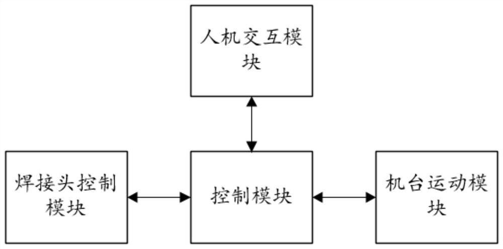
[0038] refer to figure 1 , a spot welding system, including a human-computer interaction module, a control module, a welding head control module and a machine motion module;

[0039] The human-computer interaction module is used to obtain motion parameters and send them to the control module;

[0040] The control module is used to control the motion module of the machine to move to the corresponding spot welding position according to the motion parameters, and send feedback information to the control module;

[0041] The control module is also used for sending execution information to the welding head control module according to the feedback information;

[0042] The welding head control module is used to control the welding head to perform spot welding according to the execution information.

[0043] During electric welding, place the battery and nickel sheet in the welding mold of the machine motion module, and set the motion parameters in the human-computer interaction mo...

Embodiment 2

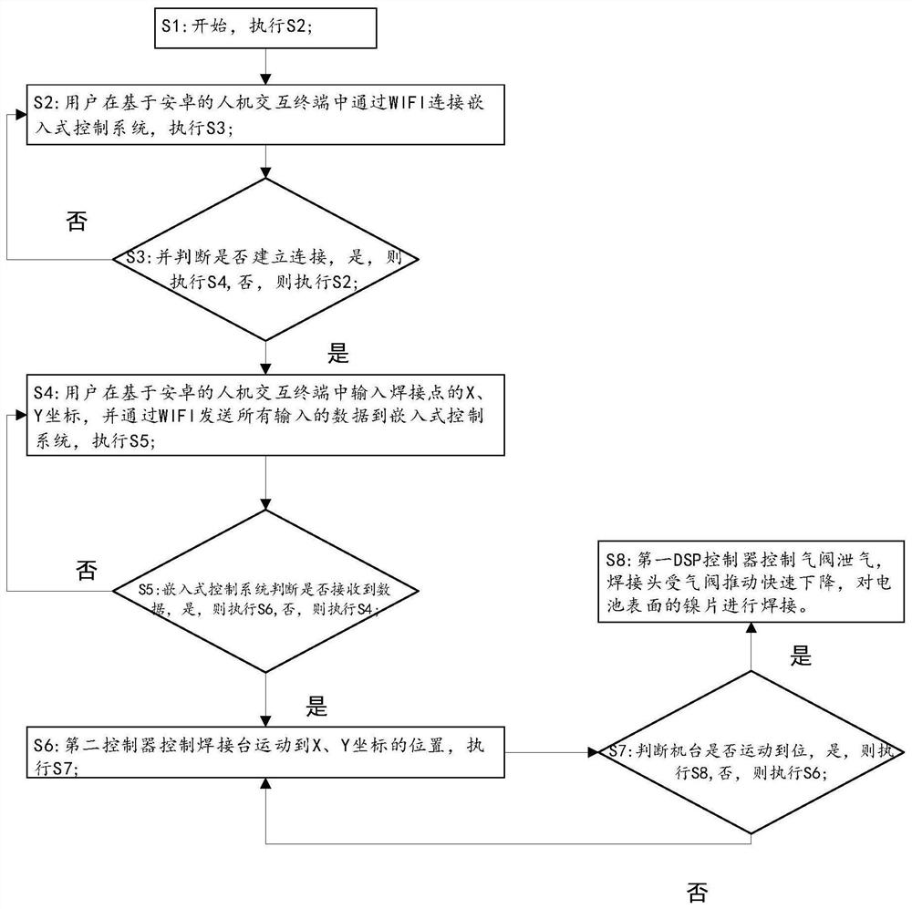
[0084] On the basis of embodiment 1, the spot welding joint control module is replaced by the first DSP controller and the pneumatic spot welding machine, and the first DSP controller is used to control the pneumatic spot welding machine to carry out spot welding, then the implementation principle of this embodiment is :

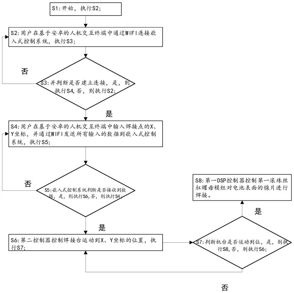
[0085] S1: start, execute S2;

[0086] S2: The user connects the embedded control system through WIFI in the Android-based human-computer interaction terminal, and executes S3;

[0087] S3: and judge whether to establish connection, if yes, then execute S4, if not, then execute S2;

[0088] S4: the user inputs the X, Y coordinates of the welding point in the human-computer interaction terminal based on Android, and sends all input data to the embedded control system through WIFI, and executes S5;

[0089] S5: The embedded control system judges whether the data is received, if yes, execute S6, otherwise, execute S4;

[0090] S6 The second controller contro...


PUM


Abstract

The invention discloses a spot welding system. The spot welding system comprises a man-machine interaction module, a control module, a welding head control module and a machine table motion module. The man-machine interaction module is used for acquiring motion parameters and sending the motion parameters to the control module; the control module is used for controlling the machine table motion module to move to a corresponding spot welding position according to the motion parameters and sending feedback information to the control module; the control module is also used for sending execution information to the welding head control module according to the feedback information; and the welding head control module is used for controlling a welding head to conduct spot welding according to theexecution information, motion parameters are set in the man-computer interaction module, the control module controls the machine table motion module to move at the position of a welding point, and then the welding head control module controls the welding head to conduct welding. The machine table motion module is adopted to transport batteries and nickel sheets which need to be welded to the position where the welding head control module can conduct welding, manual operation is reduced, the safety of workers is improved, and the welding efficiency is greatly improved.

Description

technical field [0001] The invention relates to the technical field of spot welding, in particular to a spot welding system. Background technique [0002] Spot welding has high production efficiency, easy to control welding quality, easy to realize mechanization and automation of production, and has been widely used in large-scale automatic production lines. [0003] With the development of electronic technology, electronic devices are becoming more and more miniaturized and integrated, and the demand is also increasing. The welding of micro parts not only requires precise pressure control to ensure, including small pressure stability, mechanical system In the prior art, most of the battery spot welding adopts the traditional pneumatic pressure method, and the traditional pneumatic pressure method is to manually put the batteries into the welding station for welding one by one, which is not only easy to The personal safety of the staff poses a threat, and the operation is c...

Claims


Application Information

Patent Timeline
IPC IPC(8): B23K31/02B23K37/00B23K37/02G05B19/414
CPCB23K31/02B23K37/00B23K37/0258G05B19/4142
Inventor 金礼张家刚梁邦杨
Owner GUIZHOU MINZU UNIV
Why Eureka
Try Eureka