
Full-automatic hardware assembling machine

An assembly machine and fully automatic technology, applied in metal processing, metal processing equipment, manufacturing tools, etc., can solve problems that affect the assembly efficiency of hexagonal bolts and nuts, increase the load of the rotating shaft of the assembly table, and affect the service life of the rotating shaft, etc.

Inactive Publication Date: 2020-10-23
东阳市俊华电器销售有限公司
View PDF10 Cites 2 Cited by
  • Summary
  • Abstract
  • Description
  • Claims
  • Application Information

AI Technical Summary

Problems solved by technology

[0002] Hardware refers to traditional hardware products, also known as "hardware", referring to five metals, gold, silver, copper, iron, and tin, which are artificially processed artwork or metal devices. Hardware is more widely used in modern society, such as Hardware workpieces, hardware parts, daily hardware, construction hardware and security supplies, etc., common hardware parts such as hexagonal bolts and nuts often need to be assembled together to achieve the effect of connection during use, but the existing Most of the assembly methods are manually screwing the hexagonal bolts and nuts together, which wastes time and affects the assembly efficiency of the hexagonal bolts and nuts. For example, the patent application publication number 201520502308.6 discloses a fully automatic hardware assembly machine, but There are some defects in the use of the above patents. Firstly, the assembly machine in this patent is not convenient for position change due to its large volume and mass. Secondly, the assembly table in this patent only supports the assembly table through the rotating shaft. , which greatly increases the load on the rotating shaft of the assembly table, which affects the service life of the rotating shaft

Method used


Image

  • Full-automatic hardware assembling machine
  • Full-automatic hardware assembling machine
  • Full-automatic hardware assembling machine

Examples


Embodiment Construction

[0025] The following will clearly and completely describe the technical solutions in the embodiments of the present invention with reference to the accompanying drawings in the embodiments of the present invention. Obviously, the described embodiments are only some, not all, embodiments of the present invention. Based on the embodiments of the present invention, all other embodiments obtained by persons of ordinary skill in the art without making creative efforts belong to the protection scope of the present invention.

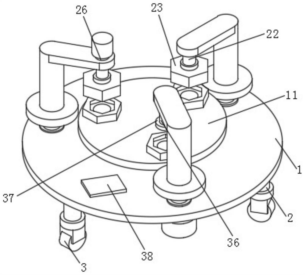
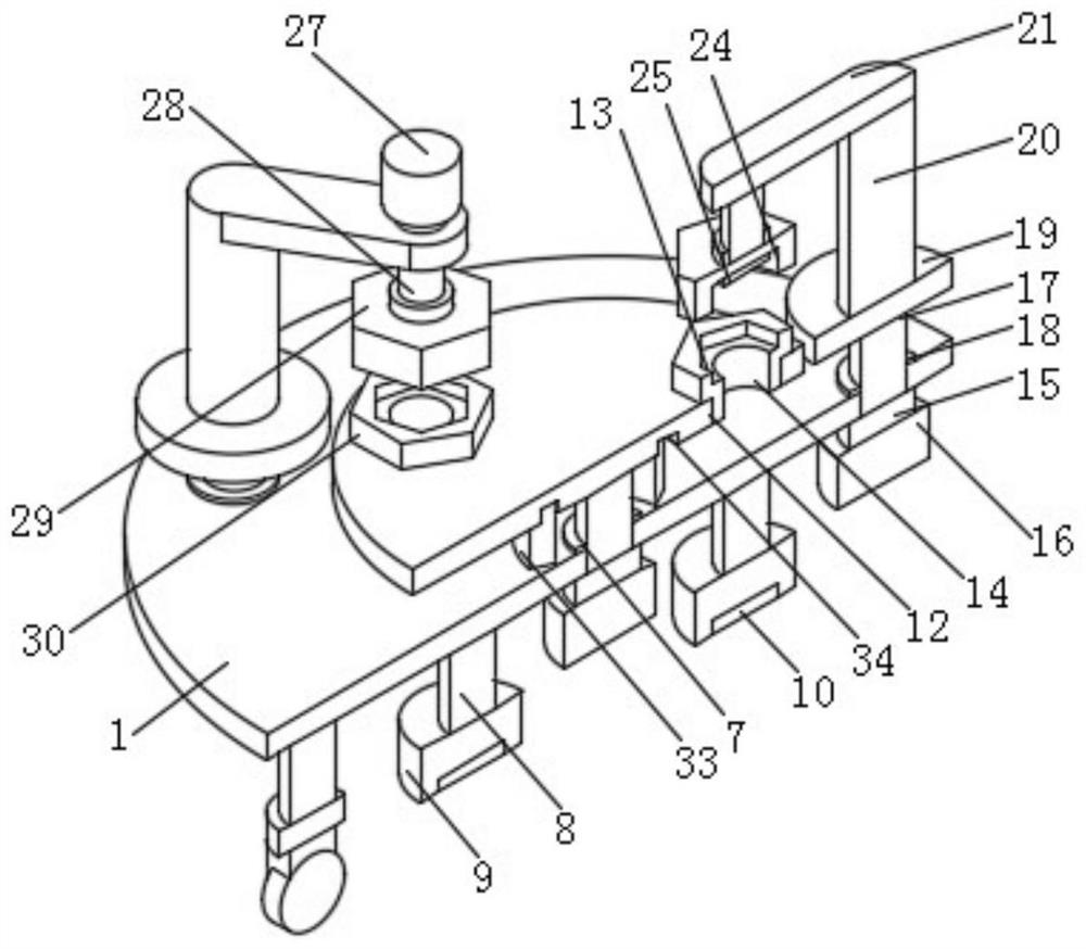
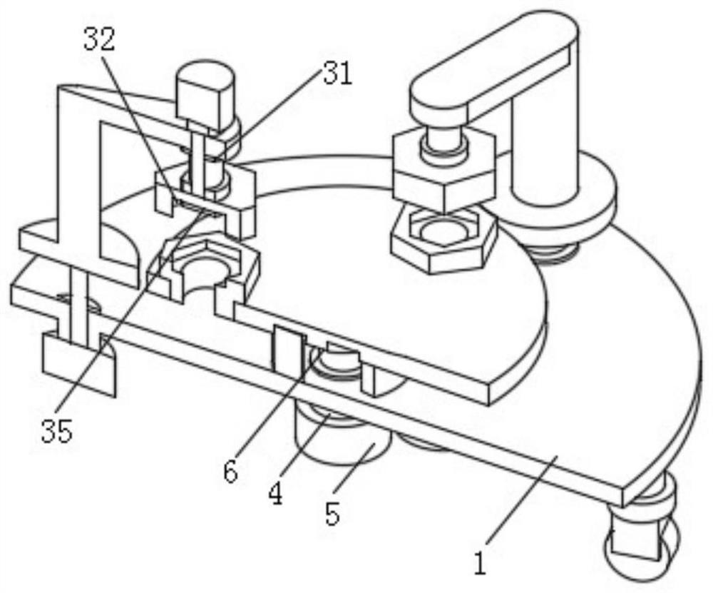
[0026] see Figure 1-3, the present invention provides a technical solution: a fully automatic hardware assembly machine, including a base 1, the edge of the lower end surface of the base 1 is provided with a leg 2, the number of the leg 2 is three, and the leg 2 is formed on the edge of the lower end face of the base 1 Distributed in a circular array, the lower ends of the legs 2 are provided with universal wheels 3, which facilitate the movement of the assem...


PUM


Abstract

The invention discloses a full-automatic hardware assembling machine. The machine comprises a base; supporting legs are arranged at the edges of the lower end surface of the base; universal wheels arearranged at the lower ends of the supporting legs; a coupling I is arranged on the middle part of the lower end surface of the base; a stepping motor I is arranged at the lower end of the coupling I;an output shaft of the stepping motor I is connected with a rotary shaft I on the base via the coupling I; and the upper end surface of the rotary shaft I is connected with the middle part of the lower end surface of an assembly plate. According to the assembling machine, a fixed arc-shaped supporting block can provide a corresponding supporting structure for the assembly plate and can effectively share the pressure on the assembly plate in the working process, the load on a rotary shaft of the assembly plate in the working process is reduced, the rotary shaft of the assembly plate is prevented from being damaged due to excessive stress in the working process, the service life of the rotary shaft of the assembly plate is guaranteed, and at the same time the arrangement that the fixed arc-shaped supporting block provides support for the assembly plate can effectively guarantee the stability of the assembly plate.

Description

technical field [0001] The invention relates to the technical field of assembly machines, in particular to a fully automatic hardware assembly machine. Background technique [0002] Hardware refers to traditional hardware products, also known as "hardware", referring to five metals, gold, silver, copper, iron, and tin, which are artificially processed artwork or metal devices. Hardware is more widely used in modern society, such as Hardware workpieces, hardware parts, daily hardware, construction hardware and security supplies, etc., common hardware parts such as hexagonal bolts and nuts often need to be assembled together to achieve the effect of connection during use, but the existing Most of the assembly methods are manually screwing the hexagonal bolts and nuts together, which wastes time and affects the assembly efficiency of the hexagonal bolts and nuts. For example, the patent application publication number 201520502308.6 discloses a fully automatic hardware assembly ...

Claims


Application Information

Patent Timeline
IPC IPC(8): B23P19/04B23P19/06B23P19/00
CPCB23P19/00B23P19/001B23P19/04B23P19/06B23P19/069
Inventor 何井芳何锦霞
Owner 东阳市俊华电器销售有限公司
Learn More