Automatic logistics conveying line

A conveying line and logistics technology, applied in the direction of transmission, transportation and packaging, roller table, etc., can solve the problems of high design cost, transmission equipment without automatic sorting, complex structure of the device, etc.

Inactive Publication Date: 2020-10-23
成都毅莘瑞科技有限公司
View PDF3 Cites 10 Cited by
  • Summary
  • Abstract
  • Description
  • Claims
  • Application Information

AI Technical Summary

Problems solved by technology

However, the structure of the above-mentioned device is complex, the design cost is high, the overall structure size is unreasonable, and it is not practical
[0005] In addition, the existing conveying equipment generally does not have the function of automatic sorting. In the process of logistics transportation, due to the different types, sizes or destinations of the goods, it is necessary to classify and plan the goods to facilitate subsequent operations. The existing technology Relying on manual sorting, the operation is time-consuming and laborious, and the degree of automation is low

Method used


Image

  • Automatic logistics conveying line
  • Automatic logistics conveying line
  • Automatic logistics conveying line

Examples


Embodiment 1

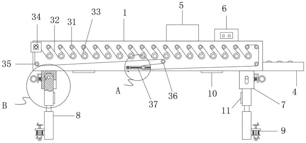
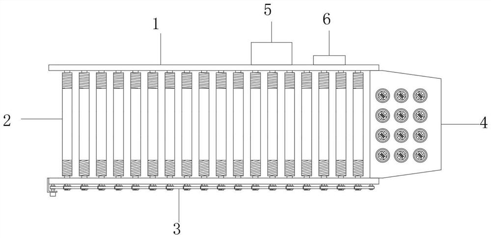
[0050] See attached figure 1 and 2 , the present invention provides a technical solution: an automatic logistics conveying line, including a frame 1, the cross section of the frame 1 is a U-shaped structure, and a conveying roller 2 is arranged to rotate in the frame 1, and there are a plurality of conveying rollers 2. Adjacent conveying rollers 2 are arranged at equal intervals, the front end of the central axis of the conveying roller 2 is connected with a roller synchronous transmission mechanism 3, the right side of the frame 1 is provided with a sorting device 4, and the right side of the rear side plate of the frame 1 is respectively A controller 5 and an identification module 6 are provided. The bottom end of the frame 1 is symmetrically provided with connecting seats 7. The connecting seats 7 on the same side are divided into two groups opposite to each other. Adjustment rollers 9 are arranged on the lower pipe wall, first magnets 10 are arranged symmetrically on the ...

Embodiment 2

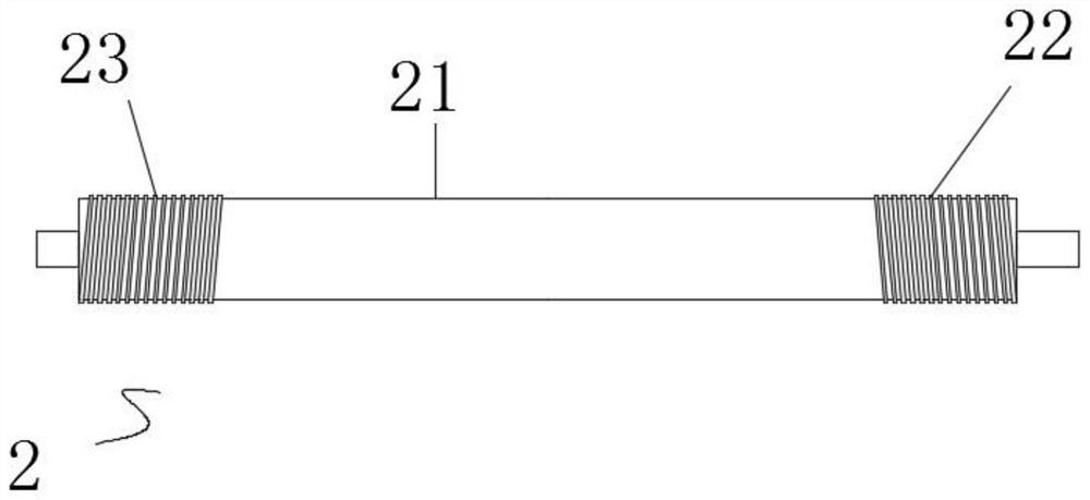
[0056] On the basis of embodiment 1, refer to the attached image 3 The conveying roller 2 includes a roller body 21, the right part of the roller body 21 is provided with a forward spiral 22, and the left part of the roller body 21 is provided with a reverse spiral 23, and the middle part of the forward spiral 22 and the reverse spiral 23 is smooth. When the cylinder body and the conveying roller 2 are normally conveyed, the cooperation of the forward spiral 22 and the reverse spiral 23 can make the conveyed goods on the conveying roller 2 tend to move towards the middle;

[0057] Specifically, because of the design of the positive and negative spirals, when the conveying roller 2 rotates under normal conditions, the positive and negative spirals will provide the force to move the goods to the middle, so when the goods are transported skewed, they can push the goods to the conveying rollers The middle part of the barrel, to avoid collision and friction between the goods and t...

Embodiment 3

[0059] On the basis of embodiment 1 or 2, refer to the attached figure 1 , the roller synchronous transmission mechanism 3 includes a first guide chain roller 31, a chain 32, a sprocket 33, a conveying motor 34, a second guide chain roller 35, a third guide chain roller 36 and a tensioning mechanism 37, 33 sets of sprockets Located at the front end of the central axis of the conveying roller 2, the first guide chain roller 31 is arranged on the front wall of the frame 1, and the first guide chain roller 31 is close to the top of the sprocket wheel 33, and there are four second guide chain rollers 35 in total. The upper and lower two are distributed at the four corners of the front side of the frame 1. The conveying motor 34 drives and connects the second guide chain roller 35 on the upper left, and there are two third guide chain rollers 36. The lower side of the middle part of the front side, the front side of the frame 1 is provided with a tensioning mechanism 37 near the th...


PUM


Abstract

The invention discloses an automatic logistics conveying line in the technical field of logistics conveying. The automatic logistics conveying line comprises a frame, the cross section of the frame isof a U-shaped structure, a plurality of conveying rollers are rotationally arranged in the frame, and the adjacent conveying rollers are arranged at equal intervals. According to the automatic logistics conveying line, by arranging forward and reverse spirals at the two ends of the conveying rollers, when goods are conveyed on the rollers and deflect, the goods are made to move towards the middleof the conveying rollers through transmission force of the spirals, therefore collision and friction between the goods and side plates of a conveying line are avoided, by arranging structures such assorting equipment and a recognition module, the conveyed goods can be classified and conveyed to a set area so as to facilitate subsequent treatment of the goods, a arranged roller synchronous transmission mechanism is in snake-shaped winding connection between a plurality of guide rollers and a roller center shaft through a chain, compared with the prior art, the design mode has the advantages that the failure rate is reduced, the rollers are stressed uniformly as well, and the movement synchronism is high.

Description

technical field [0001] The invention relates to the technical field of logistics transportation, in particular to an automatic logistics roller conveyor line. Background technique [0002] The roller conveyor is suitable for conveying all kinds of boxes, bags, pallets and other items. Bulk materials, small items or irregular items need to be transported on pallets or in turnover boxes. In today's logistics industry, roller conveyors are used in a relatively wide range. [0003] Chinese patent 203497598U discloses a synchronous conveying device for conveying rollers, including a power shaft and a conveying roller. The conveying roller includes an active conveying roller and a subsequent passive conveying roller set on the power shaft. Synchronous gears, each synchronous gear forms an overall mechanism through a synchronous belt. The utility model presses several rollers with synchronous gears to run through the synchronous belt, and drives the conveying rollers through the ...

Claims


Application Information

Patent Timeline
Patent Type & Authority Applications(China)
IPC IPC(8): B65G13/07B65G13/12F16H7/08
CPCB65G13/07B65G13/12F16H7/08
Inventor 黄波
Owner 成都毅莘瑞科技有限公司
Why Eureka
Try Eureka