Material limiting mechanism with strong stability and for discharging machine during machining

A kind of mechanical processing and strong stability technology, applied in the direction of conveyor objects, transportation and packaging, etc., can solve the problems of uneven force on the splint, reducing material stability, material falling off, etc.

Active Publication Date: 2020-10-23
浙江三禾精密机械股份有限公司
View PDF17 Cites 0 Cited by
  • Summary
  • Abstract
  • Description
  • Claims
  • Application Information

AI Technical Summary

Problems solved by technology

[0003] For example, the patent No.: CN201810983264.1 discloses a blanking device for mechanical processing, including a base plate, a base is provided above the base plate, and a sliding bar is provided in the middle of the lower side of the base, and the sliding bar and the The upper side chute of the base plate is slidingly connected, and the right side of the base plate is provided with a telescopic rod bracket, and the upper side of the telescopic rod bracket is connected with the side of the fixed end of the electric telescopic rod three, although this device can be used for large cylindrical The material is grasped and transported, but when the material with a large quality and a certain length is grasped, due to the quality and length of the workpiece, it is easy to cause uneven force on the splint inside the device, causing the material to fall off, reducing the The stability of material transportation, so there is an urgent need for a material limit mechanism for machining blanking machines with strong stability to solve the above-mentioned problems

Method used


Image

  • Material limiting mechanism with strong stability and for discharging machine during machining
  • Material limiting mechanism with strong stability and for discharging machine during machining
  • Material limiting mechanism with strong stability and for discharging machine during machining

Examples


Embodiment Construction

[0030] The following will clearly and completely describe the technical solutions in the embodiments of the present invention with reference to the accompanying drawings in the embodiments of the present invention. Obviously, the described embodiments are only some, not all, embodiments of the present invention. Based on the embodiments of the present invention, all other embodiments obtained by persons of ordinary skill in the art without making creative efforts belong to the protection scope of the present invention.

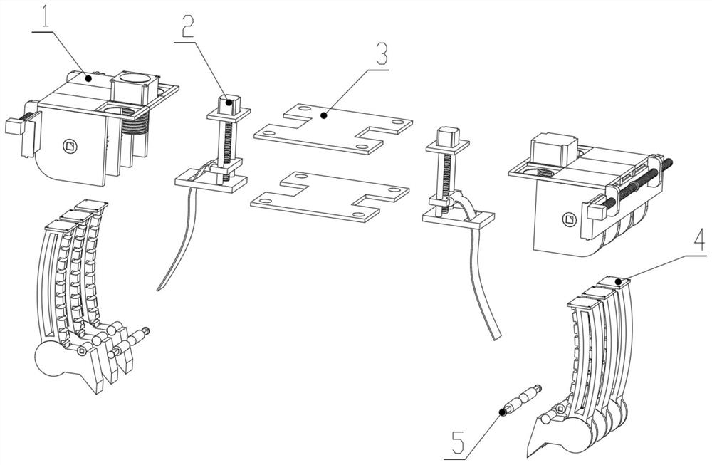
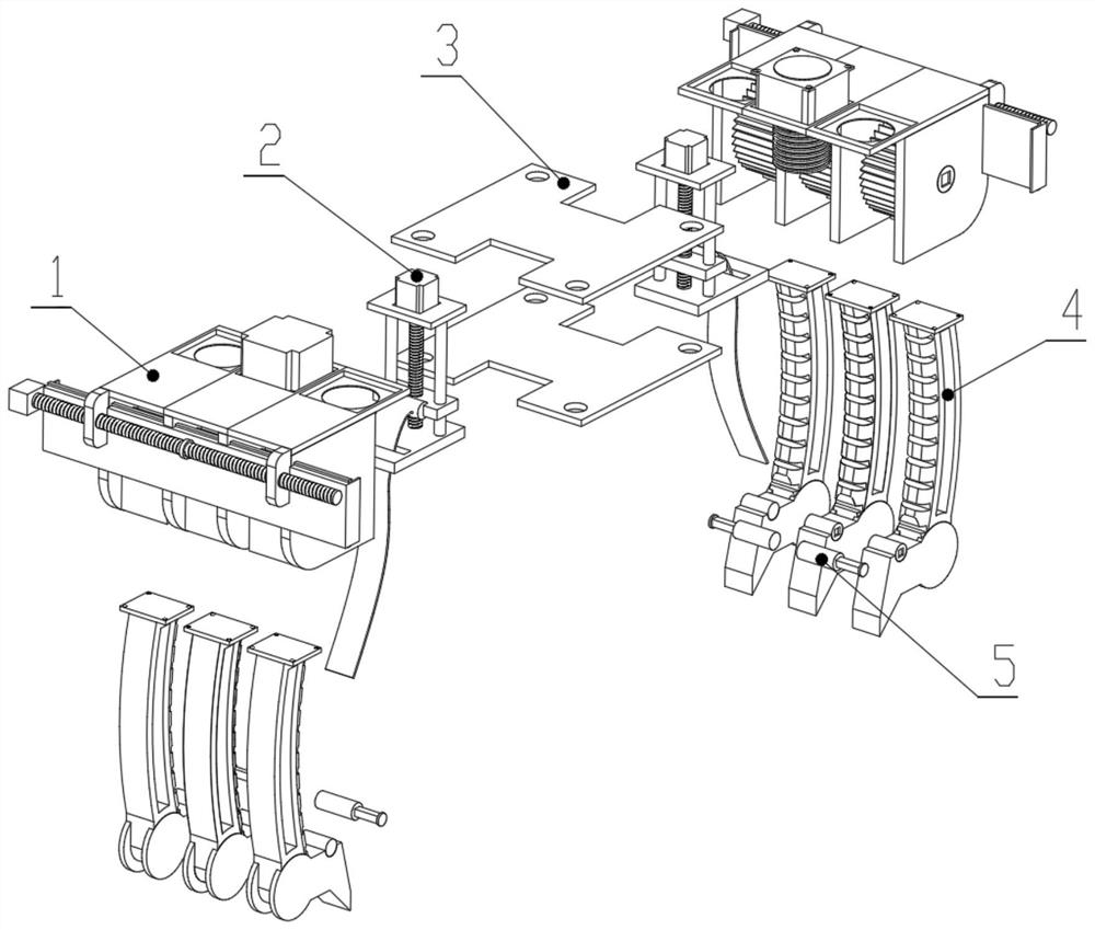
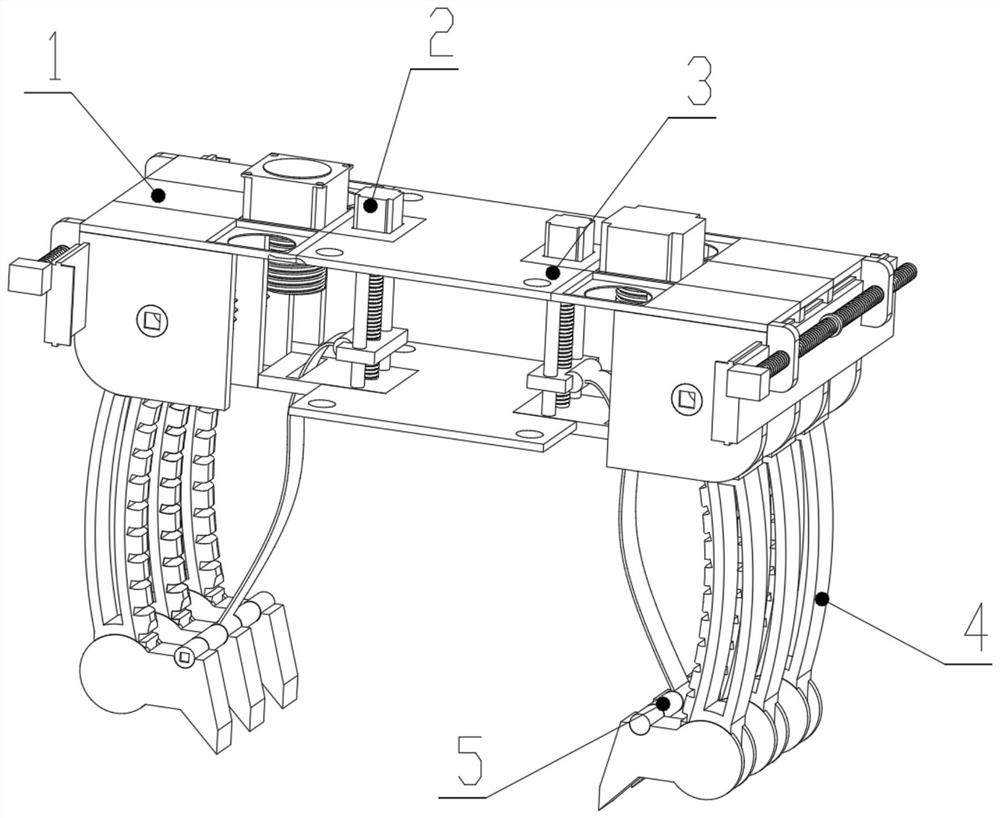
[0031] see Figure 1-9 , an embodiment provided by the present invention: a material limiting mechanism for a machining blanking machine with strong stability, including an adjusting mechanism 1, a tightening mechanism 2, a connecting plate 3, a clamping mechanism 4, a guide rod 5 and 6,

[0032] The side end surface of the connecting plate 3 is symmetrically fixedly connected with a tightening mechanism 2 for positioning, and the tightening mechanism 2 include...


PUM


Abstract

The invention discloses a material limiting mechanism with strong stability and for a discharging machine during machining. The material limiting mechanism comprises adjustment mechanisms, tighteningmechanisms, connecting plates, clamping mechanisms and guide rods, wherein the tightening mechanisms for limiting are symmetrically and fixedly connected to the side end faces of the connecting plates, and each tightening mechanism comprises a locating motor, a locating plate, a threaded clamping plate, a connecting base, a connecting belt, a first turnover shaft and a threaded shaft. According tothe material limiting mechanism, by arranging the adjustment mechanisms, the tightening mechanisms and the clamping mechanisms, the degree of freedom of a device in grabbing various materials can beeffectively increased through cooperation of the adjustment mechanisms and the clamping mechanisms, so that the adaptability of the device is stronger, and the efficiency and stability of grabbing thematerials in different shapes are improved; and meanwhile, the adjustment mechanisms can quickly adjust the working width between the clamping mechanisms, so that the grabbing width distribution of the materials by the device is broader, the device can adapt to longer and heavier materials, and the uniformity and stability of material grabbing are improved.

Description

technical field [0001] The invention relates to the technical field of machining equipment, in particular to a highly stable material limiting mechanism for a machining blanking machine. Background technique [0002] The blanking machine is an indispensable equipment in some mechanical processing industries. In the processing of materials, the blanking machine can quickly locate and transport the materials, so as to facilitate the subsequent rapid processing of materials and improve the efficiency of material processing , [0003] For example, the patent No.: CN201810983264.1 discloses a blanking device for mechanical processing, including a base plate, a base is provided above the base plate, and a sliding bar is provided in the middle of the lower side of the base, and the sliding bar and the The upper side chute of the base plate is slidingly connected, and the right side of the base plate is provided with a telescopic rod bracket, and the upper side of the telescopic ro...

Claims


Application Information

Patent Timeline
Patent Type & Authority Applications(China)
IPC IPC(8): B65G47/90
CPCB65G47/90
Inventor 陈杭峰
Owner 浙江三禾精密机械股份有限公司
Why Eureka
Try Eureka