Construction method for rotary jet prefabricating of composite pile

A construction method and technology of composite piles, applied in sheet pile walls, foundation structure engineering, construction, etc., can solve the problems that pile foundations cannot be constructed and large-scale pile foundation construction machinery cannot enter the construction site, etc.

Pending Publication Date: 2020-10-23
黑龙江辰午建筑工程有限公司
View PDF9 Cites 3 Cited by
  • Summary
  • Abstract
  • Description
  • Claims
  • Application Information

AI Technical Summary

Problems solved by technology

[0007] In order to solve the problem that the space between buildings and between buildings and other boundaries is narrow, large-scale pile foundation construction machinery cannot enter the

Method used


Image

  • Construction method for rotary jet prefabricating of composite pile
  • Construction method for rotary jet prefabricating of composite pile

Examples


specific Embodiment approach 1

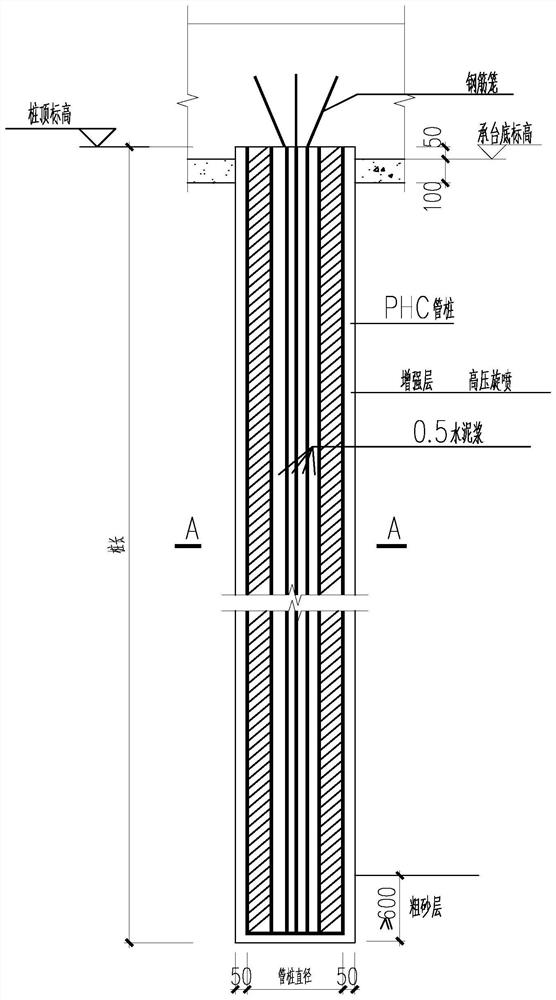
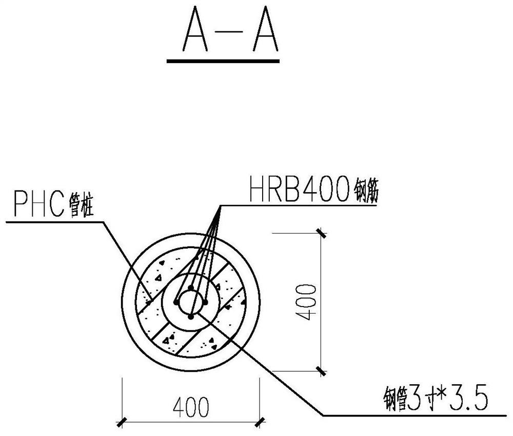
[0029] Specific implementation mode one: as figure 1 with figure 2 As shown, the construction method of the rotary spray prefabricated composite pile of the present embodiment is realized according to the following steps:

[0030] Step 1. Use rotary jet drilling rig for rotary jet drilling:

[0031] Use rotary jet drilling rigs to carry out pile drilling construction in a narrow space;

[0032] Step two, rotary jet grouting:

[0033] During the drilling process, the rotary jet drilling rig sprays the cement slurry through the bottom of the rotary jet drilling rig bit to ensure that the cement slurry is fully stirred after filtering, and the working pressure range of the spraying grout when the rotary jet drilling rig drills in is 7 ~ 10mpa; to ensure that the rotary jet drilling rig The jet grouting pressure is 25-28Mpa when the drill bit is lifted; part of the fine sand in the cement slurry is discharged out of the pile hole along with the cement slurry, and the gap withi...

specific Embodiment approach 2

[0038] Specific embodiment 2: In step 1 of this embodiment, the grouting pressure of the grouting grout is controlled to be 2-4 mpa.

[0039] In this way, the cement slurry has the function of penetration and cementation, and the pressure injection of the cement slurry can increase the resistance of the side of the pile and the resistance of the pile end. Other components and connections are the same as those in the first embodiment.

specific Embodiment approach 3

[0040] Embodiment 3: The water-cement ratio of the cement slurry in Step 1 of this embodiment ranges from 0.5 to 0.8.

[0041] In this way, the strength of the cement slurry is guaranteed, the side resistance of the pile is improved, and the virtual soil at the bottom of the pile is solidified. Other components and connections are the same as those in the second embodiment.


PUM


Abstract

The invention discloses a construction method for rotary jet grouting prefabricating of a composite pile, and relates to a pile foundation construction method. The method solves the problem that due to a narrow space between buildings or between a building and other boundary, a large pile foundation construction machine cannot enter a construction site, so that a pile foundation cannot be constructed. Rotary jet grouting drilling is performed by a rotary jet grouting drilling machine; rotary jet grouting of cement paste is performed in the drilling process of the rotary jet grouting drilling machine by a drill bit of the rotary jet grouting drilling machine, and part of fine-grained sand is discharged out of a hole at the bottom of the rotary jet grouting drilling machine along with the cement paste; the drill bit of the rotary jet grouting drilling machine is slowly lifted at a constant speed, and it is ensured that the lifting speed of the drill bit of the rotary jet grouting drilling machine is lower than a matched grouting amount until the drill bit of the rotary jet grouting drilling machine is completely lifted out of a drilled hole; a prefabricated pile is inserted in the drilled hole by a press or a vibration impact hammer, it is ensured that the pile continuously sinks in place, that is, the prefabricated pile sinks in the pile hole to an elevation state; and the cement paste is cured to form stone and cement so as to closely wrap the prefabricated pile to obtain the composite pile of cement soil and the prefabricated pile. The construction method is used for pilefoundation construction in a narrow space.

Description

technical field [0001] The invention relates to a construction method of a rotary spray prefabricated composite pile. Background technique [0002] With the rapid development of my country's construction industry, there are various forms of foundation, and concrete pouring piles are widely used. [0003] Previously, when a construction company in Harbin was constructing in the foundation pit, because part of the building body was constructed first, a narrow space was formed between the building body and the stairs, and between the building body and the side wall of the foundation pit, and large pile foundation construction machinery could not enter. At the construction site, the pile foundations in this part of the space and near the building cannot be constructed. This technology was invented to solve this problem. [0004] Machines with small size and high flexibility can enter narrow spaces, such as rotary jet drilling rigs, pulling machines, etc., but due to power and ...

Claims


Application Information

Patent Timeline
IPC IPC(8): E02D5/30E02D5/46E02D5/50E02D7/18E02D7/20
CPCE02D5/30E02D5/46E02D5/50E02D7/18E02D7/20E02D2250/003E02D2300/0023E02D2300/002
Inventor 张连波王常青邹延辉苏君树闫滨
Owner 黑龙江辰午建筑工程有限公司
Why Eureka
Try Eureka