Unlock instant, AI-driven research and patent intelligence for your innovation.
Continuous conduit type coring equipment
What is Al technical title?
Al technical title is built by PatSnap Al team. It summarizes the technical point description of the patent document.
A catheter and equipment technology, which is applied in the field of continuous catheter coring equipment, can solve the problems of actual error of coring components, high height, unsuitable working environment with limited space and height, etc.
Pending Publication Date: 2020-10-23
SICHUAN UNIV
View PDF3 Cites 5 Cited by
Summary
Abstract
Description
Claims
Application Information
AI Technical Summary
This helps you quickly interpret patents by identifying the three key elements:
Problems solved by technology
Method used
Benefits of technology
Problems solved by technology
The inlet of the existing coiled tubing injection head is located directly above the outlet, and the injection head itself has a certain height, coupled with the height of the guide gooseneck, resulting in a high height of the entire equipment, which is not suitable for the working environment with limited space height ( For example, coal mine roadway, the general height does not exceed 3m)
[0005] In addition, in order to further realize pressure-holding coring of coal seams, a patent document with a publication number of CN201811862U discloses an underground pressure-relief sealed coal core sampler, which relies on mucus and vacuum devices to perform pressure-holding coring of samples. There is a fluid medium in the coal seam, which will cause certain pollution to the coal seam core and affect the determination of parameters such as water content
[0006] The coring device is usually composed of an inner tube assembly and an outer tube assembly. There is a gap between the inner tube assembly and the outer tube assembly, so that the coring cylinder is easy to rotate with the coring outer cylinder. When the external disturbance is large, There may be a large error between the coring composition and the real situation
In order to reduce the error caused by rotation, currently used coring devices are often provided with a single-action device between the outer tube assembly and the inner tube assembly to reduce the rotation of the core cylinder, but although the single-action device has anti-rotation effect, it cannot The anti-rotation effect is limited, and it is difficult to effectively reduce the measurement error
Method used
Image
Click on the blue label to locate the original text in one second.
Reading with bidirectional positioning of images and text.
Examples
Embodiment 1
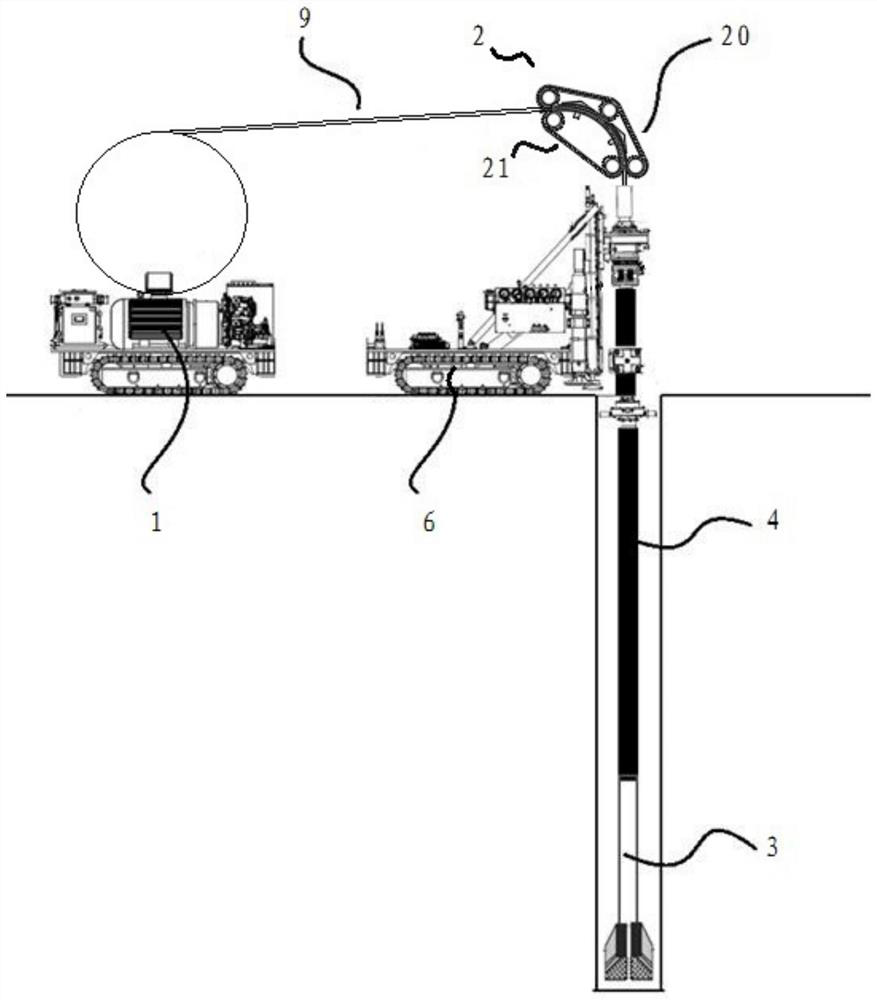
[0061] like figure 2 As shown, the continuous conduit type coring equipment disclosed in this embodiment includes a continuous conduit operation device, a tunnel drilling machine 6 and a core extractor 3 .
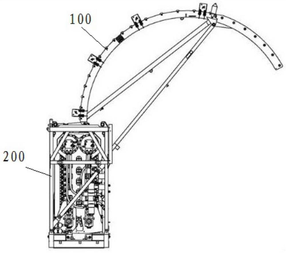
[0062] The continuous conduit operation device includes a reel device 1 , an operation vehicle, a continuous conduit 9 and an integrated guide and injection mechanism 2 .
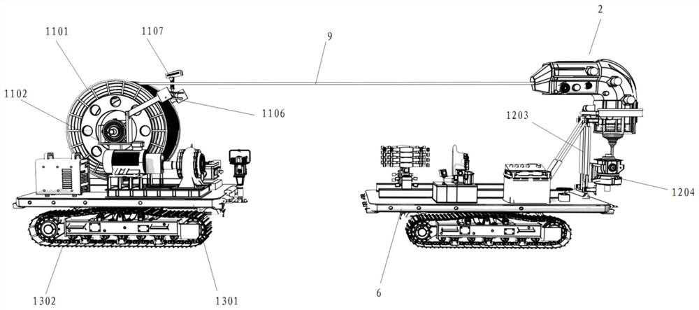
[0063] like figure 2 , 3 , 4, 5, the reel device 1 is installed on the work vehicle for receiving the continuous conduit 9 . The reel device 1 includes a reel 1101 and a reel stand 1102. The reel 1101 is set on the reel stand 1102, and the reel stand 1102 is provided with a pipe arrangement assembly. The work vehicle includes a base 1301 and a crawler running mechanism 1302 , and the crawler running gear 1302 is arranged at the bottom of the base 1301 .
[0144] The difference between this embodiment and Embodiment 1 is that: Figure 19 As shown, the second sprocket chain clamping assembly 21 in this embodiment also includes a second tensioning pulley 24 engaged with the second chain 213, the second driving pulley 211, the second tensioning pulley 24 and the second driven pulley 212 Not in a straight line.
[0145] In this embodiment, an arc-shaped guide nipple 5 is provided at the entrance of the catheter guide passage, and the arc-shaped guide nipple 5 guides the continuous catheter 9 to enter the catheter guide passage more smoothly. The arc-shaped guide short joint 5 is concentric with the catheter guide channel and has the same radius.
[0146] The arc-shaped guide nipple 5 is located below the entrance of the guide channel of the guide tube, and has a certain supporting effect on the continuous guide tube 9 .
Embodiment 3
[0148] The difference between this embodiment and embodiment one or embodiment two is: as Figure 20 As shown, in this embodiment, the first push plate 205 is connected with a clamping driving device 22 for driving it to move in the radial direction.
[0149] The guiding and injecting integrated mechanism of the present invention integrates guiding and injecting functions, and adds a straightening device, which can ensure no increase in downhole wear while effectively reducing the height of the equipment. The invention is especially suitable for working environments with limited space and height, such as working in coal mine roadways.
PUM
Abstract
The invention relates to continuous conduit type coring equipment which comprises a coring device and a continuous conduit operation device. The coring device comprises an inner pipeassembly and an outer pipeassembly, and the inner pipeassembly can be connected with the outer pipe assembly in a clamping manner; the outer pipe assembly comprises an outer pipe and a drill bit arranged on the outer pipe, and the inner pipe assembly comprises an inner pipe component and a central rod; the inner pipe component comprises a core inner cylinder, a core outer cylinder and a pressure retaining valvearranged at the bottom of the core outer cylinder; and the continuous conduit operation device comprises a continuous conduit and a guiding and injecting integrated mechanism capable of pulling the continuous conduit down or out, wherein the continuous conduit is used for lowering and lifting the inner pipe assembly. The pressure maintaining coring device is lifted up and lowered by using the continuous conduit operation device, a cable can penetrate in the continuous conduit conveniently transmit measurement and control signals, and real-time measurement of hole bottom parameters is facilitated; the guiding and injecting integrated mechanism integrates a guiding function and an injecting function, a guide gooseneck can be omitted, and the height of the equipment can be effectively reduced; and the equipment is particularly suitable for operation environments with the limited space height.
Description
technical field [0001] The invention relates to the technical field of underground exploration, in particular to a continuous conduit type coring equipment. Background technique [0002] my country is not only a big coal producer, but also a big coalconsumer. Coal is an important basic energy and raw material for our country. Coal seam gas content and coal seam gas pressure are the main indicators of outburst coal seam outburst risk area prediction and regional effect inspection. Coal seam gas content is usually measured by ground coal seam gas content measurement, geological survey gas content measurement, coal seam drilling and coring in underground mines, etc. Due to the differences in the test conditions and methods of coal seam gas content, the test results of the above coal seam gas content often have large differences and low accuracy, and there are widespread estimation losses, which have limited guiding significance for coal mining. [0003] For coal seam tunnel c...
Claims
Application Information
Patent Timeline
Application Date:The date an application was filed.
Publication Date:The date a patent or application was officially published.
First Publication Date:The earliest publication date of a patent with the same application number.
Issue Date:Publication date of the patent grant document.
PCT Entry Date:The Entry date of PCT National Phase.
Estimated Expiry Date:The statutory expiry date of a patent right according to the Patent Law, and it is the longest term of protection that the patent right can achieve without the termination of the patent right due to other reasons(Term extension factor has been taken into account ).
Invalid Date:Actual expiry date is based on effective date or publication date of legal transaction data of invalid patent.
