Fault self-diagnosis vertical oil pumping unit and oil pumping unit fault self-diagnosis control method

A self-diagnosis and pumping unit technology, applied in supporting machines, mechanical equipment, earthwork drilling, etc., can solve problems such as failure of pumping units to achieve self-checking.

Active Publication Date: 2020-10-23
合立智能装备有限责任公司
View PDF14 Cites 0 Cited by
  • Summary
  • Abstract
  • Description
  • Claims
  • Application Information

AI Technical Summary

Problems solved by technology

[0003] The present invention provides a fault self-diagnosis vertical pumping unit and a fault self-diagnosis control method of the pumping unit, which overcomes the above-mentioned deficiencies in the prior art, and can effectively solve the problem that the existing pumping unit cannot realize fault self-diagnosis

Method used


Image

  • Fault self-diagnosis vertical oil pumping unit and oil pumping unit fault self-diagnosis control method
  • Fault self-diagnosis vertical oil pumping unit and oil pumping unit fault self-diagnosis control method
  • Fault self-diagnosis vertical oil pumping unit and oil pumping unit fault self-diagnosis control method

Examples


Embodiment 1

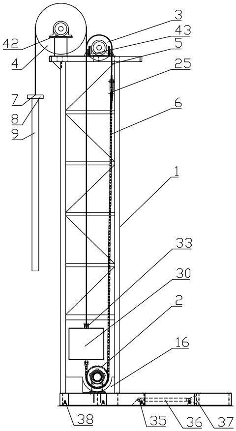
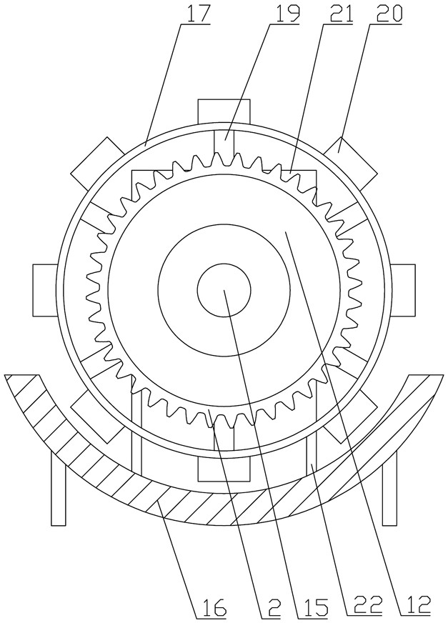
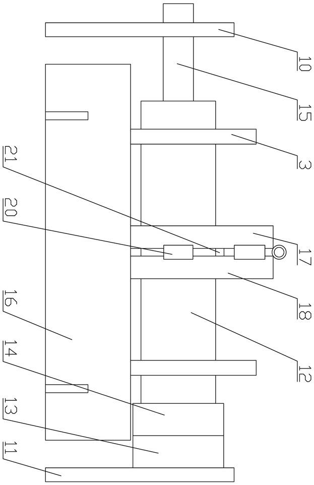
[0034] Embodiment one: as attached figure 1 , 2 , 3, 4, 5, 6, 7, 8, 9, and 10, the fault self-diagnosis vertical pumping unit includes a tower 1, a sprocket 2, a winch 3, a sky wheel 4, a connecting rope 5, a connecting Chain 6, oil pumping rope 7, rope hanger 8, first rope chain connector, second rope chain connector, intelligent control module and driving device, the bottom of the tower frame 1 is provided with a driving device, and the output end of the driving device is fixedly installed There is a sprocket 2, the top of the tower 1 corresponding to the position above the sprocket 2 is provided with a winch 3, the top of the tower 1 corresponding to the left position of the winch 3 is provided with a sky wheel 4, the sprocket 2, the winch 3 and the sky wheel The axis of 4 is distributed along the front and rear directions, and the outer side of the lower part of the sprocket wheel 2 is provided with a U-shaped connecting chain 6 whose upper part is located above it and ha...

Embodiment 2

[0046] Embodiment two: as attached figure 1 As shown, a pumping unit fault self-diagnosis control method using the above-mentioned fault self-diagnosis vertical pumping unit comprises the following steps:

[0047] S1: the control module controls the rotation direction, rotation speed and start / stop of the hydraulic motor 13, and the control module controls the flow rate pumped into the hydraulic motor 13 by the hydraulic station;

[0048] S2: The control module receives the weight data signal of the sucker rod 9, the upper limit position signal and the lower limit position signal of the second rope chain connector, wherein the weight data signal of the sucker rod 9 is collected by the load sensor, and the second rope chain connection The upper limit position signal of the part is collected by the upper limit switch, and the lower limit position signal of the second rope chain connector is collected by the lower limit switch;

[0049] S3: The load sensor transmits the weight d...


PUM


Abstract

The invention relates to the technical field of oil pumping unit intelligent control, in particular to a fault self-diagnosis vertical oil pumping unit and an oil pumping unit fault self-diagnosis control method. The fault self-diagnosis vertical oil pumping unit comprises a tower, a chain wheel, a reel, a head sheave, a connecting rope, a connecting chain, an oil pumping rope, a beam hanger, a first rope chain connecting piece, a second rope chain connecting piece, an intelligent control module and a driving device; and the driving device is arranged at the bottom of the tower, and the chainwheel is fixedly mounted at the output end of the driving device. The oil pumping unit fault self-diagnosis control method comprises the steps that the control module controls the rotating direction,the rotating speed, starting and stopping of a hydraulic motor, and the control module controls the flow pumped into the hydraulic motor by a hydraulic station. The fault self-diagnosis vertical oil pumping unit is reasonable and compact in structure and ingenious in concept, through cooperation of the intelligent control module and the driving device, oil pumping unit fault self-diagnosis is achieved, and the characteristics of stability, high efficiency and intelligence are achieved.

Description

technical field [0001] The invention relates to the technical field of intelligent control of pumping units, and relates to a fault self-diagnosis vertical pumping unit and a fault self-diagnosis control method for the pumping unit. Background technique [0002] During the operation of the pumping unit, the sucker rod will break off or stick. Since the sucker rod is running underground, the failure phenomenon is often not found at the first time, resulting in damage to the equipment and loss of production. . Contents of the invention [0003] The invention provides a fault self-diagnosis vertical pumping unit and a fault self-diagnosis control method of the pumping unit, which overcomes the above-mentioned deficiencies in the prior art and can effectively solve the problem that the existing pumping unit cannot realize fault self-diagnosis. [0004] One of the technical solutions of the present invention is achieved through the following measures: a vertical oil pumping un...

Claims


Application Information

Patent Timeline
Patent Type & Authority Applications(China)
IPC IPC(8): E21B43/00E21B43/12E21B19/02E21B47/008F16N7/16F16N39/06F16M3/00F16F15/28
CPCE21B43/126E21B19/02F16N7/16F16N39/06F16M3/00F16F15/28
Inventor 陈金余王新愚庞涛
Owner 合立智能装备有限责任公司
Why Eureka
Try Eureka