Turbine flowmeter

A technology of turbine flowmeter and inertial measurement unit, which is applied in the hydraulic field, can solve the problems of single function and large size, and achieve the effect of excellent signal quality, compact structure and small volume

Pending Publication Date: 2022-01-07
HARBIN UNIV OF SCI & TECH
View PDF0 Cites 0 Cited by
  • Summary
  • Abstract
  • Description
  • Claims
  • Application Information

AI Technical Summary

Problems solved by technology

[0003] The present invention provides a turbine flowmeter to solve the problem of large size and single function of the existing turbine flowmeter

Method used


Image

  • Turbine flowmeter
  • Turbine flowmeter
  • Turbine flowmeter

Examples


specific Embodiment approach

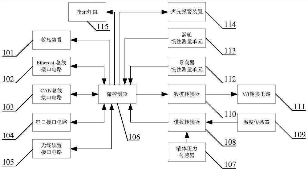
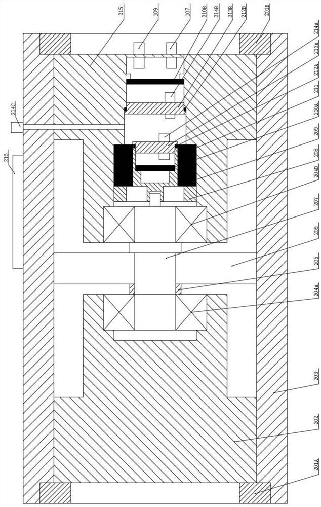
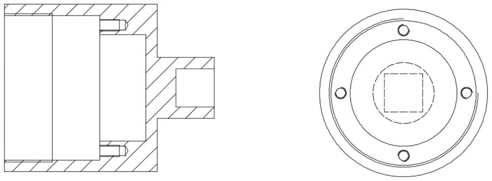
[0026] Specific implementation method: the following combination figure 1 , figure 2 and image 3 Explain the principle of turbine flowmeter. A turbine flowmeter according to the present invention comprises a digital display device (101), an EtherCAT bus interface circuit (102), a CAN bus interface circuit (103), a serial port interface circuit (104), a wireless device interface circuit (105), Microcontroller (106), liquid pressure sensor (107), analog-to-digital converter (108), temperature sensor (109), digital-to-analog converter (110), V / I conversion circuit (111), pilot inertial measurement unit (112), turbine inertial measurement unit (113), sound and light alarm device (114), indicator light group (115), lock nut (201A), (201B), front guide (202), housing (203) , bearing (204A), (204B), guide sleeve (205), turbine (206), turbine shaft (207), conductive slip ring lock nut (208), conductive slip ring (209), circuit board (210A), (210B), rotational inertial measuremen...


PUM


Abstract

The invention provides a turbine flowmeter, belongs to the field of hydraulic pressure, and mainly solves the problems that an existing turbine flowmeter is large in size and single in function. Flow measurement, temperature detection, pressure detection and fault diagnosis functions are integrated, turbine rotating speed measurement and vibration information acquisition are performed by using the inertial measurement unit, and signal analysis is performed by using the microprocessor. The turbine flowmeter has the advantages of being compact in structure, small in size, complete in function, high in signal quality and rich in transmission interface, and the overall performance of the flow meter is improved.

Description

Technical field: [0001] The invention relates to a turbine flowmeter, which belongs to the field of hydraulic pressure. Background technique: [0002] Turbine flowmeters are mainly used to measure liquid flow. Existing turbine flowmeters measure turbine speed through a magnetoelectric sensor, and obtain flow information on this basis, and their functions are relatively single. Since the magnetoelectric sensor is perpendicular to the axis of the turbine, the existing turbine flowmeter has a relatively large overall size and cannot be used in a narrow space. Invention content: [0003] The invention provides a turbine flowmeter to solve the problems of large size and single function of the existing turbine flowmeter. [0004] A turbine flowmeter according to the present invention comprises a digital display device (101), an EtherCAT bus interface circuit (102), a CAN bus interface circuit (103), a serial port interface circuit (104), a wireless device interface circuit (105...

Claims


Application Information

Patent Timeline
Patent Type & Authority Applications(China)
IPC IPC(8): G01F1/32G01F25/00G01K13/02G01L11/00G01P15/02
CPCG01F25/00G01K13/02G01L11/00G01P15/02
Inventor 孙桂涛时献江
Owner HARBIN UNIV OF SCI & TECH
Why Eureka
Try Eureka