Steam turbine rotor and steam turbine

A technology of steam turbines and rotors, which is applied in the directions of machines/engines, mechanical equipment, engine components, etc., and can solve problems such as scattering of implanted fins

Active Publication Date: 2020-10-23
MITSUBISHI HEAVY IND LTD
View PDF6 Cites 0 Cited by
  • Summary
  • Abstract
  • Description
  • Claims
  • Application Information

AI Technical Summary

Problems solved by technology

However, since the implanted fins and the rotor are not integrally structured, there is a possibility that the implanted fins may fly apart if the pull-out strength of the implanted fins is lower than the centrifugal force of the rotor.

Method used


Image

  • Steam turbine rotor and steam turbine
  • Steam turbine rotor and steam turbine
  • Steam turbine rotor and steam turbine

Examples


Embodiment 1

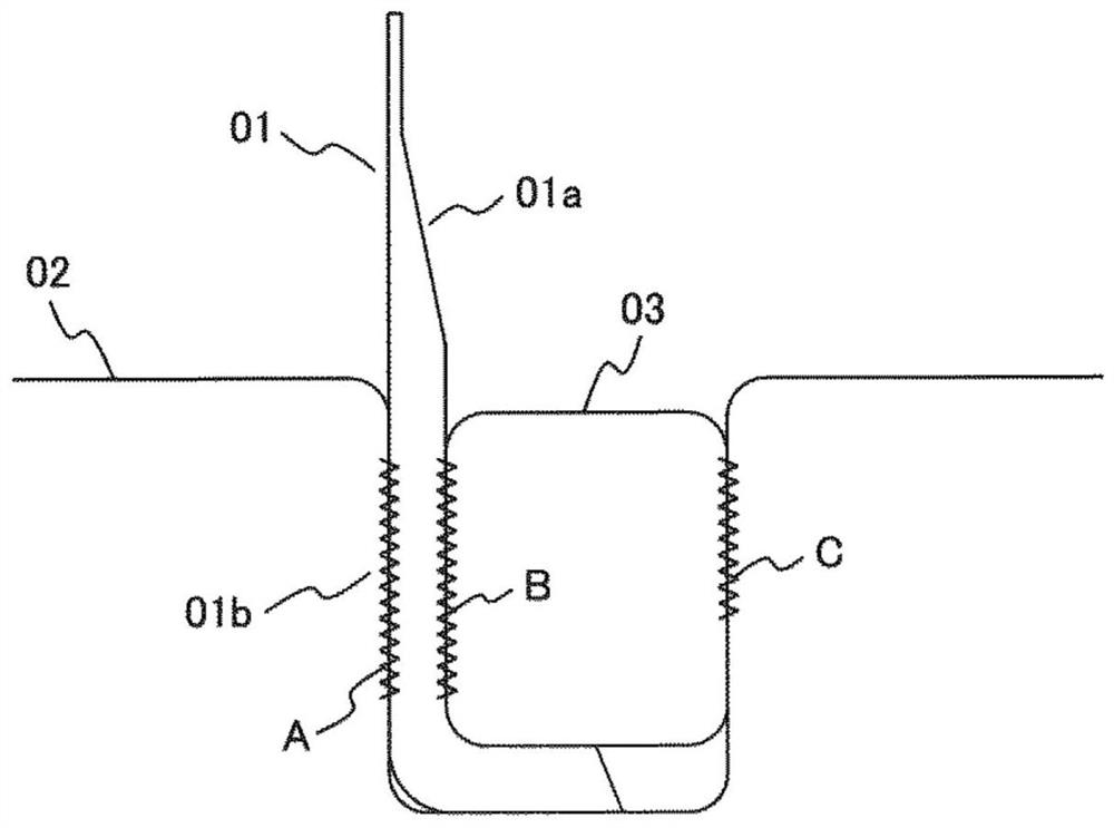
[0022] figure 1 It is a schematic diagram explaining the implanted fin which does not have the wedge-shaped groove described in this Example.

[0023] In order to prevent steam (operating fluid) from flowing from the gap (interval) formed between the inner peripheral surface (not shown) of the stationary body and the outer peripheral surface of the rotating body (steam turbine rotor) (hereinafter referred to as "rotor") 02, the steam turbine Leakage, set the sealing fins.

[0024] In particular, there are two types of seal fins provided on the rotor side: chipped fins formed by processing the rotor and implanted fins fixed to grooves formed in the rotor.

[0025] The sealing fins described in this embodiment are implanted fins. The implant fin 01 has a replaceable structure, so when the tip is damaged, it can be replaced with a new implant fin 01 and the sealing performance can be restored.

[0026] The implanted fin 01 described in this embodiment is a fin made by bending ...

Embodiment 2

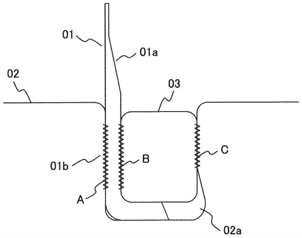
[0050] figure 2 It is a schematic diagram explaining the implanted fin having a wedge-shaped groove described in this embodiment, and is a cross-sectional view.

[0051] This embodiment differs from the first embodiment in that the fixing groove 04 has a wedge-shaped groove 02a. That is, the rotor 02 described in this embodiment is different from the first embodiment in that the fixing groove 04 has the wedge-shaped groove 02a.

[0052] Thus, in this embodiment, the wedge-shaped groove 02a is provided in the fixing groove 04, and the locking strip 03 enters the wedge-shaped groove 02a, whereby the pull-out strength of the implanted fin 01 can be further improved.

Embodiment 3

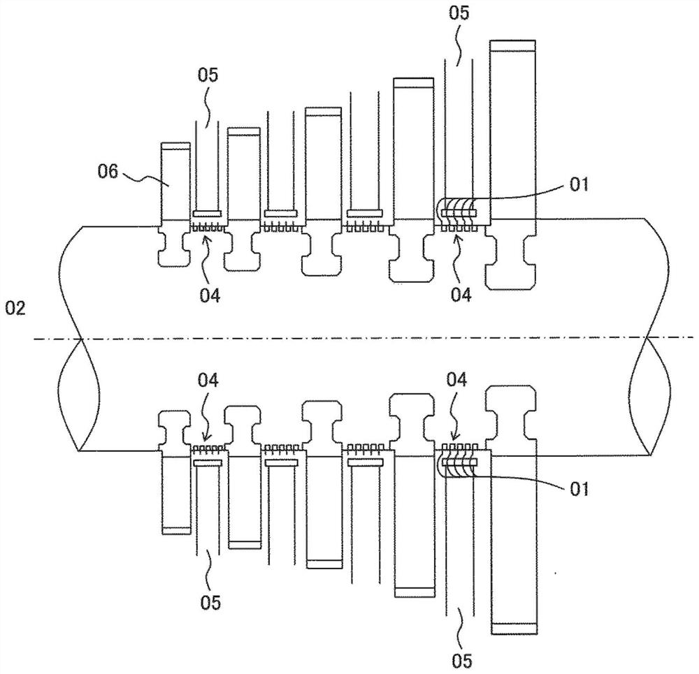
[0054] image 3 It is a schematic diagram explaining the steam turbine described in this embodiment.

[0055] The steam turbine described in this embodiment has a rotor 02 , moving blades 06 provided on the rotor 02 , stationary blades 05 , and implanted seal fin portions 04 .

[0056] The stator blades 05 expand the steam to impart velocity energy to the steam, change the flow direction of the steam, and generate momentum in the rotation direction.

[0057] The implanted seal fin 01 is provided on the implanted seal fin part 04 , and the implanted seal fin 01 is provided so that steam does not leak from between the tip of the stator blade 05 and the rotor 02 .

[0058] The moving blades 06 are arranged on the rotor 02 to transform the thermal energy retained by the steam into the rotational energy of the rotor 02 .

[0059] By providing the implanted fins 01 described in the first or second embodiment on the rotor 02 of such a steam turbine, a steam turbine with improved re...


PUM


Abstract

The invention provides a steam turbine rotor and a steam turbine. The steam turbine rotor has excellent drawing strength corresponding to, for example, high temperature of steam, large diameter of a rotor shaft and the like. A steam turbine rotor according to the present invention has implanted fins inserted into fixing grooves. The implanted fin is composed of a bent bottom part and a vertical part which is provided with a fin front end part and a fin root part. The implanted fin is fixed to the fixing groove through the locking strip steel, and therefore the static friction coefficient between the side face of the fixing groove and the side face of the fin root portion, the static friction coefficient between the side face of the locking strip steel and the side face of the fin root portion and the static friction coefficient between the side face of the fixing groove and the side face of the locking strip steel are increased.

Description

technical field [0001] The invention relates to a steam turbine rotor with implanted fins and to a steam turbine. Background technique [0002] A steam turbine is provided with sealing fins to prevent leakage of steam (operating fluid) from a gap (interval) formed between an inner peripheral surface of a stationary body and an outer peripheral surface of a rotating body (rotor). [0003] In particular, there are two types of seal fins provided on the rotor side: chipped fins formed by processing the rotor and implanted fins fixed to grooves formed in the rotor. [0004] Among them, the implanted fin has a replaceable structure, so when the tip of the implanted fin is damaged, it can be replaced with a new implanted fin and the sealing performance can be restored. However, since the implanted fins and the rotor are not integrally structured, there is a possibility that the implanted fins may be scattered when the pulling strength of the implanted fins is lower than the centr...

Claims


Application Information

Patent Timeline
Patent Type & Authority Applications(China)
IPC IPC(8): F01D11/02
CPCF01D11/02F01D11/001F05D2240/55F01D5/005F16J15/3268F16J15/44F16J15/4472F05D2230/64F05D2220/31F01D5/147F01D5/30F05D2240/30
Inventor 及川慎司泉岳志佐藤顺濑川清簗濑祐太
Owner MITSUBISHI HEAVY IND LTD
Why Eureka
Try Eureka