
A fan coil unit for air-conditioning air supply system

An air supply system and fan coil technology, applied in the field of air conditioning system equipment, can solve the problems of reducing air supply efficiency and quality, affecting air supply efficiency, increasing wind resistance, etc., so as to improve air supply efficiency and quality, and improve the degree of mutual interference Low, low flow rate loss effect

Active Publication Date: 2021-10-22
DEZHOU ZHONGWEI AIR CONDITIONING EQUIP
View PDF0 Cites 0 Cited by
  • Summary
  • Abstract
  • Description
  • Claims
  • Application Information

AI Technical Summary

Problems solved by technology

[0004] However, when the existing fan coil units are used, there are the following problems. Since the inner fan coils (surface coolers) are arranged in a staggered manner relative to the air intake airflow, when the fan is running at a high speed and the gas flow rate is relatively high, it will act on each staggered The degree of turbulence between the airflow behind the coil is relatively large. When the coil produces resistance to the high-speed airflow, the degree of flow velocity loss of the high-speed airflow increases, thereby reducing the efficiency and quality of the air supply. Moreover, the fan coil The inside of the pipe is a rectangular space, and the space is large, and the size of the gas output pipe is smaller than the internal rectangular space of the fan coil unit, which makes it easy to form local turbulence inside the fan coil unit, resulting in increased wind resistance and affecting the air supply efficiency

Method used


Image

  • A fan coil unit for air-conditioning air supply system
  • A fan coil unit for air-conditioning air supply system
  • A fan coil unit for air-conditioning air supply system

Examples


Embodiment Construction

[0022] The following will clearly and completely describe the technical solutions in the embodiments of the present invention with reference to the accompanying drawings in the embodiments of the present invention. Obviously, the described embodiments are only some, not all, embodiments of the present invention. Based on the embodiments of the present invention, all other embodiments obtained by persons of ordinary skill in the art without making creative efforts belong to the protection scope of the present invention.

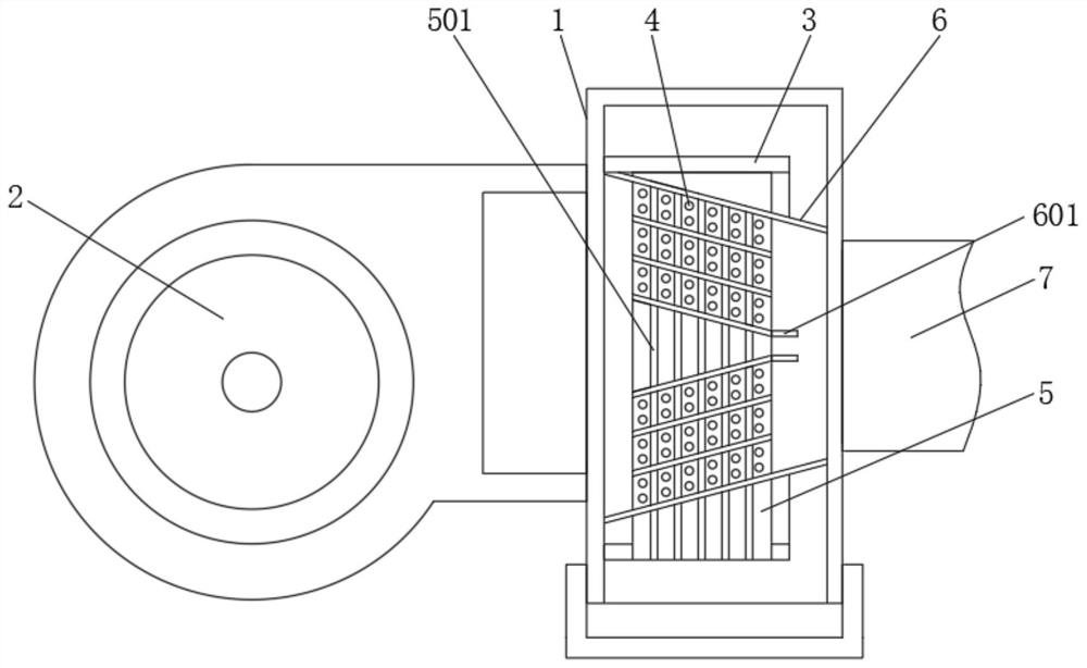
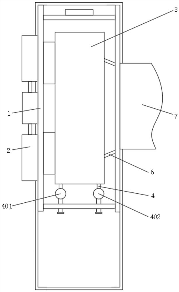
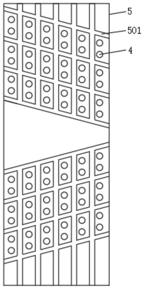
[0023] see Figure 1-5 , a fan coil unit for air-conditioning air supply systems, including a chassis 1, two fans 2 are provided on the side of the chassis 1, and the two fans 2 are driven to rotate by a double-axis motor, and the interior of the chassis 1 is fixedly installed The installation box 3 of the surface cooler, a number of condensate conduits 4 are fixedly set between the two side walls of the installation box 3 of the surface cooler, and both ends ...


PUM


Abstract

The invention relates to the field of air-conditioning system equipment, and discloses a fan coil unit used in an air-conditioning air supply system, which includes a chassis. Two fans driven by biaxial motors are arranged on the side of the chassis. There is an air supply pipe, and the installation box of the surface cooler is arranged inside the cabinet, and the surface cooler is arranged between the inner walls of both sides of the installation box of the surface cooler, and the surface cooler is composed of several condensate pipes, fins , Composition of deflectors. When the fan is running at a high speed, the high-speed air flow passes through the channels between the fins and the deflectors in the surface cooler, and the high-speed air flow is divided, so that the high-speed air flow between the fins and the deflectors is closely related to the The degree of turbulence formed behind the condensate conduit is average, and the degree of mutual interference in the overall space is low, which effectively reduces the air resistance of the high-speed air flow passing through the condensate conduit, thereby reducing the flow rate loss of the high-speed air flow and improving the air supply. efficiency and quality.

Description

technical field [0001] The invention relates to the field of air-conditioning system equipment, in particular to a fan coil unit used in an air-conditioning air supply system. Background technique [0002] Fan coil unit is one of the terminal devices in the entire air conditioning system. When chilled water or hot water flows through the coil tube, it exchanges heat with the air outside the tube, so that the air is cooled, dehumidified or heated to adjust the indoor air parameters. It is mainly composed of It is composed of low-noise motor, coil (surface cooler), condensation pan, air filter, air inlet and outlet, controller, etc. [0003] The working principle of the existing fan coil unit is as follows: the heat exchange medium is transported into the coil tube and circulated. The air sucked into the room by the fan through the air return port crosses the coil, exchanges heat with the cold (hot) medium water in the coil, cools down and dehumidifies, and then is sent into ...

Claims


Application Information

Patent Timeline
Patent Type & Authority Patents(China)
IPC IPC(8): F24F1/0007F24F1/0063F24F13/30F24F13/22
CPCF24F1/0007F24F13/222F24F13/30F24F1/0063
Inventor 张传义张永琪胡晓军
Owner DEZHOU ZHONGWEI AIR CONDITIONING EQUIP
Learn More