Non-contact infrared thermal imaging device for high-temperature oven and thermal compensation method thereof

An infrared thermal imaging and non-contact technology, which is applied in the field of non-contact infrared thermal imaging temperature measurement, can solve the problems of temperature error, high error, inability to accurately judge the accurate temperature of food, and inability to transmit heat well.

Active Publication Date: 2020-10-23
绍兴晨璞网络科技有限公司
View PDF9 Cites 1 Cited by
  • Summary
  • Abstract
  • Description
  • Claims
  • Application Information

AI Technical Summary

Problems solved by technology

[0003] (1) Only one weighted temperature value in the box can be obtained, the error is extremely high, and the exact temperature of the food cannot be accurately judged, so that better temperature control power control cannot be achieved;
[0004] (2) Infrared attenuation problem caused by infrared transmission lens
If the thickness of the infrared transmission lens is very thin, the heat in the box will damage the infrared temperature sensor through the lens; The ability attenuation is very heavy, and the error is extremely high;
[0005] (3) When the thickness of the infrared transmission lens is very thick, it will also emit a lot of infrared energy, which will cause errors in the final obtained temperature;
[0006] (4) It cannot work in a high-temperature environment (400°C to 600°C), and the high-temperature oven will damage the infrared temperature sensor through the lens;
[0007] (5) When the temperature of the working environment is too high or the temperature is unstable, the infrared temperature sensor device will be affected by thermal breakdown, resulting in extremely poor temperature measurement accuracy or even unusable

Method used


Image

  • Non-contact infrared thermal imaging device for high-temperature oven and thermal compensation method thereof
  • Non-contact infrared thermal imaging device for high-temperature oven and thermal compensation method thereof
  • Non-contact infrared thermal imaging device for high-temperature oven and thermal compensation method thereof

Examples


Embodiment Construction

[0057] The technical solution of this patent will be described in further detail below in conjunction with specific embodiments.

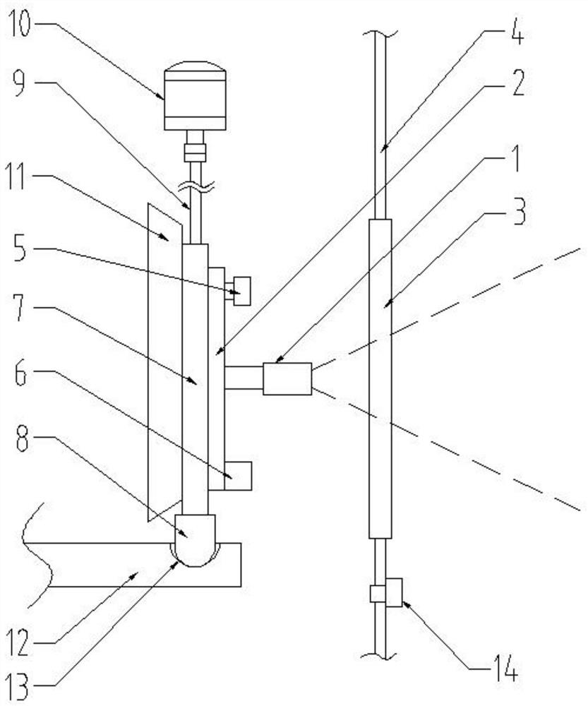
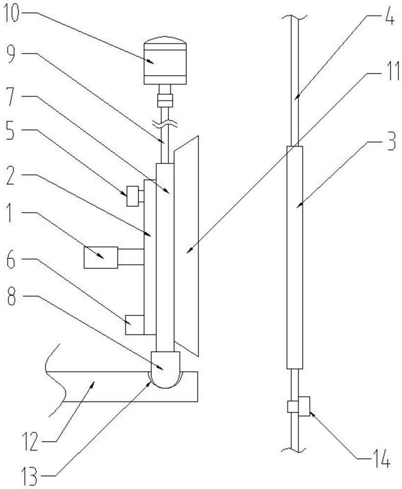
[0058] Embodiments of the present patent are described in detail below, examples of which are shown in the drawings, wherein the same or similar reference numerals designate the same or similar elements or elements having the same or similar functions throughout. The embodiments described below by referring to the figures are exemplary and are only used for explaining the patent, and should not be construed as limiting the patent.

[0059] In the description of this patent, it is to be understood that the terms "center", "upper", "lower", "front", "rear", "left", "right", "vertical", "horizontal", The orientation or positional relationship indicated by "top", "bottom", "inner", "outer", etc. is based on the orientation or positional relationship shown in the drawings, and is only for the convenience of describing this patent and simplifying the des...


PUM

PropertyMeasurementUnit
optical propertiesaaaaaaaaaa
transmittivityaaaaaaaaaa

Abstract

The invention provides a non-contact infrared thermal imaging device for a high-temperature oven and a thermal compensation method thereof, belongs to the technical field of non-contact infrared thermal imaging temperature measurement, and is used for solving the technical problem that accurate temperature measurement is difficult to perform in the high-temperature oven. According to the invention, by rotating the external thermal imaging sensor and related components, the working environment temperature of the infrared thermal imaging sensor is prevented from being too high or unstable; the working temperature stability of the infrared thermal imaging sensor can be ensured by adopting a rotary snapshot mode; the infrared transmission lens which is thin and high in transmittance is adopted, infrared capability attenuation obtained by the external thermal imaging sensor is little, errors are greatly reduced, temperature data can be accurately collected by the infrared thermal imaging sensor, and therefore a reliable temperature system and system emissivity with good linearity are achieved. The temperature of food in the oven is accurately obtained through a thermal and temperature compensation algorithm, the precision is high, and the problem that an infrared thermal imaging sensor cannot be accurately applied to obtain the temperature in a high-temperature oven environment is effectively solved.

Description

technical field [0001] The invention belongs to the technical field of non-contact infrared thermal imaging temperature measurement, and relates to a non-contact infrared thermal imaging device for a high-temperature oven and a thermal compensation method thereof. Background technique [0002] Existing infrared temperature measurement technologies applied to microwave ovens and low-temperature ovens (100°C to 150°C) almost all use infrared sensors to directly measure the temperature inside the microwave oven through lenses, so they will face the following problems: [0003] (1) Only one weighted temperature value in the box can be obtained, the error is extremely high, and the exact temperature of the food cannot be accurately judged, so that better temperature control power control cannot be achieved; [0004] (2) The infrared attenuation problem caused by the infrared transmission lens. If the thickness of the infrared transmission lens is very thin, the heat in the box w...

Claims


Application Information

Patent Timeline
Patent Type & Authority Applications(China)
IPC IPC(8): G01J5/00G01J5/02G01J5/06G01J5/08
CPCG01J5/0003G01J5/0275G01J5/06G01J5/0806G01J2005/0077G01J5/064G01J5/80Y02P60/80
Inventor 张若璞
Owner 绍兴晨璞网络科技有限公司
Why Eureka
Try Eureka