High-power cooling tower of rapid power concentration motor train unit

A power concentration, cooling tower technology, applied in water shower coolers, transformer/inductor cooling, electrical component structure associations, etc., can solve the problems of inability to constantly monitor the running status of components, inconvenient installation and disassembly, and numerous auxiliary structures. , to achieve the effect of simple structure, low manufacturing cost and improved anti-corrosion ability

Pending Publication Date: 2020-03-24
HUNAN LIANCHENG TRACK EQUIP CO LTD
View PDF0 Cites 0 Cited by
  • Summary
  • Abstract
  • Description
  • Claims
  • Application Information

AI Technical Summary

Problems solved by technology

Centralized power EMUs are more compact in structure and have higher requirements for structural design. However, in the design of cooling towers at home and abroad, there are still complex structures, numerous auxiliary structures, low space utilization, inconvenient installation and disassembly, and high noise. Constantly monitor the running status of components, effectively prevent system failures, and high maintenance costs

Method used


Image

  • High-power cooling tower of rapid power concentration motor train unit
  • High-power cooling tower of rapid power concentration motor train unit
  • High-power cooling tower of rapid power concentration motor train unit

Examples


Embodiment Construction

[0030] The embodiments of the present invention will be described in detail below with reference to the accompanying drawings, but the present invention can be implemented in various ways defined and covered by the claims.

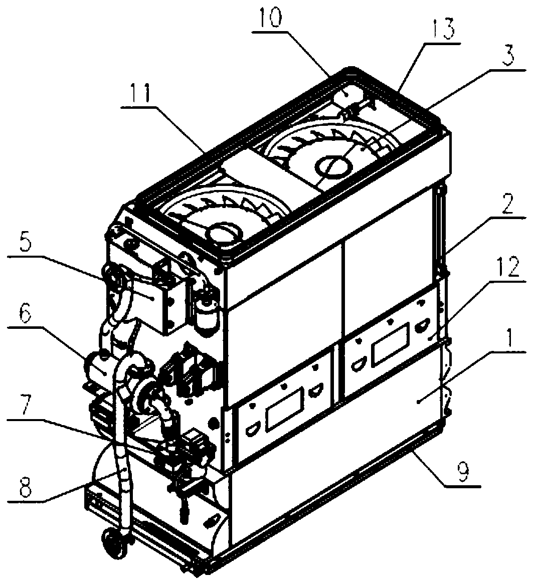
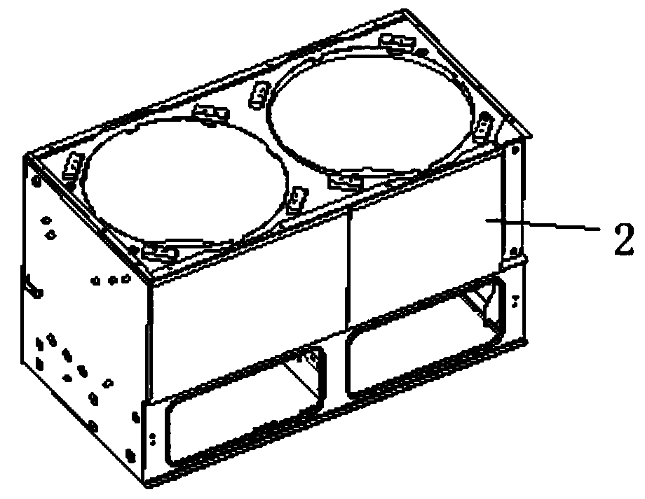
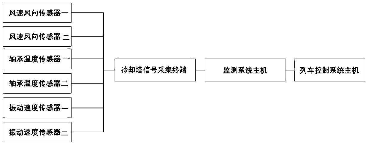
[0031] see Figure 1 to Figure 4 , a high-power cooling tower for high-speed concentrated EMUs, including a top cover 10, a frame 2, a cooling fan 3, a heat exchanger 1, a base 9, a shielded pump 6, an expansion tank 5, a water pipeline, a relay 7 and an online detection device, The top cover 10, the frame 2, the heat exchanger 1, and the base 9 form the external channel of the cooling tower in sequence from top to bottom, and the top cover 10, the frame 2, the heat exchanger 1 and the base 9 Connected by fasteners; the cooling fan 3 is arranged inside the frame 2, and the shielded pump 6, the expansion tank 5 and the relay 7 are arranged on the side wall of the frame 2;

[0032] The water inlet chamber of the heat exchanger 1 is connected to the water ou...


PUM


Abstract

The invention provides a high-power cooling tower of a rapid power concentration motor train unit. The high-power cooling tower comprises a top cover, a rack, a cooling fan, a heat exchanger, a base,a shield pump, an expansion water tank, an oil pipeline, a water pipeline, a relay and an online detection device, wherein the top cover, the rack, the heat exchanger and the base sequentially form anair cooling channel of the cooling tower from top to bottom; the cooling fan is arranged in the rack, and the shield pump, the expansion water tank and the relay are arranged on the side wall of therack. A water inlet cavity of the heat exchanger is connected with a water outlet pipe of a traction converter, a water outlet cavity of the heat exchanger is connected with a water inlet pipe of theshield pump, a water outlet pipe of the shield pump is connected with a water inlet pipe of the traction converter, and the oil pipeline is connected with a traction transformer. The cooling tower issimple in structure, light in weight, convenient to maintain, low in noise, intelligent and capable of synchronously cooling the traction converter and the traction transformer.

Description

technical field [0001] The invention relates to the technical field of cooling devices for vehicles, in particular to a high-power cooling tower for high-speed power concentrated EMUs. Background technique [0002] With the rapid development of domestic rail transit, especially for the integration and reliability of centralized power EMUs, extremely high requirements are put forward, including the performance and reliability requirements for traction converters and traction transformers. Main equipment for traction converter and traction transformer cooling. Centralized power EMUs are more compact in structure and have higher requirements for structural design. However, in the design of cooling towers at home and abroad, there are still complex structures, numerous auxiliary structures, low space utilization, inconvenient installation and disassembly, and high noise. Constantly monitor the operating status of components, effectively prevent system failures, and high mainten...

Claims


Application Information

Patent Timeline
Patent Type & Authority Applications(China)
IPC IPC(8): F28C1/00F28F27/00H01F27/08H01F27/16H01F27/12H01F27/40
CPCF28C1/00F28F27/003H01F27/08H01F27/085H01F27/12H01F27/16H01F27/40H01F27/402H01F2027/406
Inventor 胡金润李友瑜陈尧王先海
Owner HUNAN LIANCHENG TRACK EQUIP CO LTD
Why Eureka
Try Eureka