
Method for predicting internal ballistic performance of solid rocket engine

A solid rocket and motor technology, applied in geometric CAD, design optimization/simulation, special data processing applications, etc., can solve the problem of low prediction accuracy of internal ballistic performance, increased development time and cost, and regardless of the impact of internal ballistic performance, etc. question

Active Publication Date: 2020-10-23
广州中科宇航探索技术有限公司
View PDF4 Cites 7 Cited by
  • Summary
  • Abstract
  • Description
  • Claims
  • Application Information

AI Technical Summary

Problems solved by technology

[0004] The first one does not consider the effect of ablation of the thermal insulation layer on the internal ballistic performance
This scheme is suitable for engines with short working hours, low combustion chamber pressure, and good ablation resistance of the heat insulation layer, and the engine has no strict requirements on the accuracy of internal ballistic prediction. Low, only suitable for small and medium solid rocket motors
The defect of this scheme is that it is impossible to explain the difference between the prediction results of the internal ballistic performance of the engine that has not undergone the ignition test and the measured internal ballistic performance, and multiple ground ignition tests will inevitably increase the development time and development cost

Method used


Image

  • Method for predicting internal ballistic performance of solid rocket engine
  • Method for predicting internal ballistic performance of solid rocket engine
  • Method for predicting internal ballistic performance of solid rocket engine

Examples


Embodiment Construction

[0045] The technical solutions in the embodiments of the present application are clearly and completely described below in combination with the drawings in the embodiments of the present application. Obviously, the described embodiments are part of the embodiments of the present application, not all of them. Based on the embodiments in this application, all other embodiments obtained by those skilled in the art without making creative efforts belong to the scope of protection of this application.

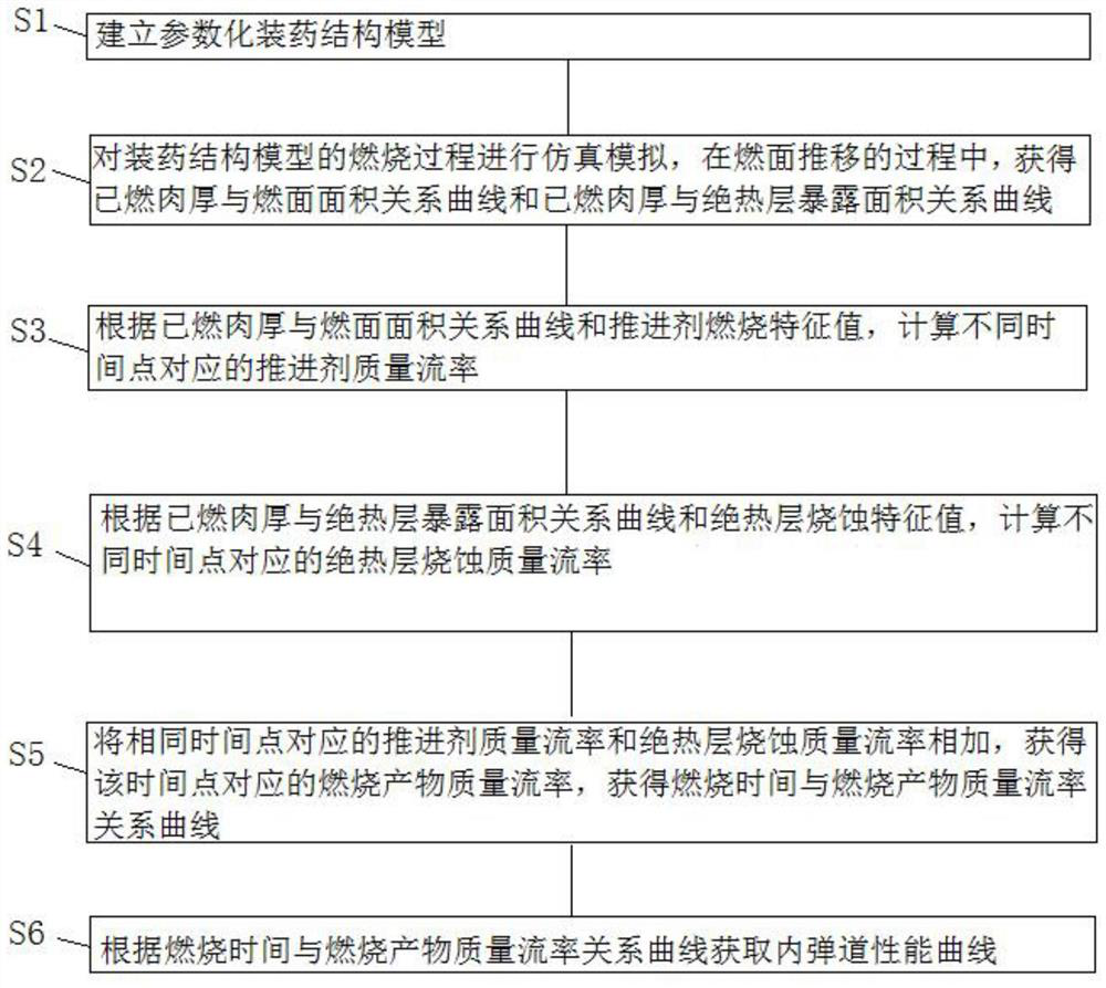
[0046] Such as figure 1 As shown, the application provides a method for predicting the internal ballistic performance of a solid rocket motor, the method comprising the steps of:

[0047] Step S1, establishing a parametric charge structure model.

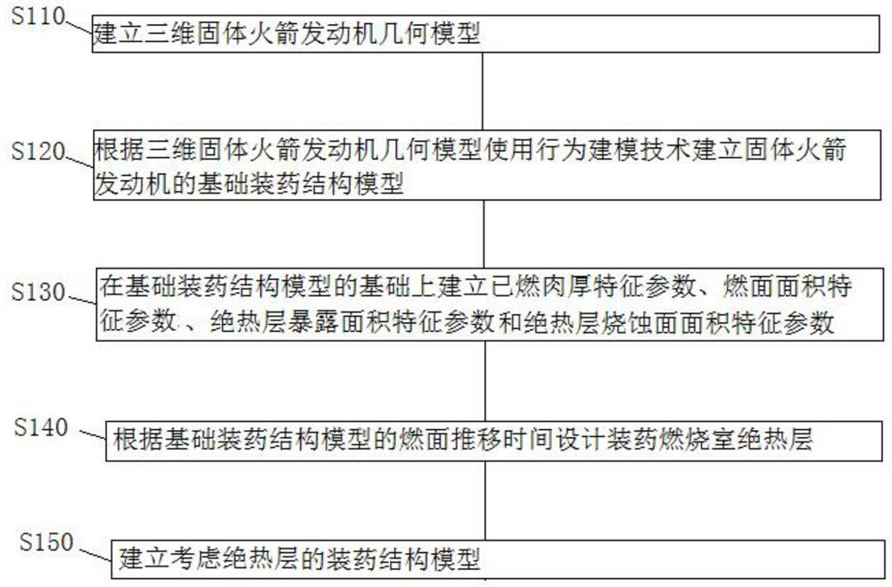
[0048] Such as figure 2 As shown, step S1 includes the following sub-steps:

[0049] Step S110, establishing a three-dimensional solid rocket motor geometric model.

[0050] In step S120, a basic charge structure model of the solid r...


PUM


Abstract

The invention provides a method for predicting internal ballistic performance of a solid rocket engine. The method comprises the following steps of: establishing a parameterized charging structure model; carrying out analogue simulation on the combustion process of the charging structure model, and outputting a relation curve between combusted thickness and a combustion surface and a relation curve between the combusted thickness and the exposed area of a heat insulation layer; calculating propellant mass flow rates corresponding to different time points according to the relation curve of thecombusted thickness and the area of the combustion surface, calculating the ablation mass flow rates of the heat insulation layer corresponding to the different time points according to the relation curve of the combusted thickness and the exposure area of the heat insulation layer, adding the propellant mass flow rate and the ablation mass flow rate of the heat insulation layer corresponding to the same time point, and outputting the relation curve of time and combustion product mass flow rates; and obtaining an internal ballistic performance curve according to the relation curve of the combustion time and the combustion product mass flow rates. The method obviously improves the prediction precision of the internal ballistic performance in of solid rocket engine before a ignition test, optimizes the performance of the solid rocket engine, and reduces the development time and development cost.

Description

technical field [0001] The present application relates to the technical field of dynamic ablation of thermal insulation layers of solid rocket motors, in particular to a method for predicting internal ballistic performance of solid rocket motors. Background technique [0002] During the working process of the solid rocket motor, the combustion of the charge produces a large amount of high-temperature and high-pressure gas, which is accelerated by the expansion of the nozzle to form a supersonic gas flow and is ejected. According to the conservation of mass, in the state of pressure balance in the engine room, if the insulation layer and other components are not considered The mass flow rate of the nozzle inlet is equal to the propellant combustion mass flow rate. [0003] Before the ground ignition experiment, there are usually two options for predicting the internal ballistic performance of solid rocket motors: [0004] The first one does not consider the influence of the ...

Claims


Application Information

Patent Timeline
IPC IPC(8): G06F30/20G06F30/17
CPCG06F30/20G06F30/17
Inventor 张翔赖谋荣史晓宁李秦峰宋丽丽杨毅强
Owner 广州中科宇航探索技术有限公司
Learn More