
Voltage compensation structure of third winding of variable-flux voltage-regulating autotransformer and transformer

An autotransformer, voltage compensation technology, applied in the direction of transformer/inductor coil/winding/connection, transformer/inductor components, circuits, etc. Three windings etc.

Pending Publication Date: 2020-10-23
SHANDONG POWER EQUIP
View PDF0 Cites 0 Cited by
  • Summary
  • Abstract
  • Description
  • Claims
  • Application Information

AI Technical Summary

Problems solved by technology

With the increase of the voltage level of the common winding, the manufacturing difficulty and price of the transformer tap changer are higher. When the insulation level of the common winding exceeds the manufacturing level of the existing switch, the conventional line-side voltage regulation structure is no longer applicable; In the neutral point voltage regulation mode, the voltage regulating winding is connected in series at the end of the series winding and the common winding. When the gear position of the switch changes, in order to keep the voltage of the series winding and the common winding constant, the magnetic flux in the iron core changes with the adjustment of the switch gear. , will cause the third winding voltage to fluctuate
In addition, in order to improve the short-circuit resistance of the third winding, it is usually necessary to increase the capacity of the third winding, which increases the manufacturing cost of the transformer.

Method used


Image

  • Voltage compensation structure of third winding of variable-flux voltage-regulating autotransformer and transformer

Examples


Embodiment Construction

[0018] Below in conjunction with accompanying drawing, the embodiment of the present invention is described in detail:

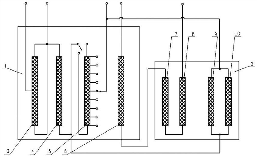
[0019] In the existing flux-changing autotransformer, the magnetic fluxes of the body 1 of the main transformer and the body 2 of the compensation transformer are relatively independent, and the voltage regulating winding 5 of the main transformer is connected with the first excitation winding 9 and the second excitation winding 9 of the compensation transformer. Windings 10 are connected in parallel. The voltage regulating winding 5 of the main transformer is located at the end of the common winding 4. When the gear of the switch is adjusted, the magnetic flux density in the iron core will change (variable flux voltage regulation), thereby causing the voltage fluctuation of the third winding 6. In order to keep the voltage of the third winding 6 constant, it is necessary to design a compensation winding connected in series with the third winding for compens...


PUM


Abstract

The invention relates to a voltage compensation structure of a third winding of a variable-flux voltage-regulating autotransformer. A first compensation winding and a second compensation winding are arranged in a compensation transformer body, and the third winding in a main transformer body is connected with the first compensation winding and the second compensation winding in series. The invention further relates to a variable-flux voltage-regulating autotransformer and a voltage compensation structure applying the third winding, the variable-flux voltage-regulating autotransformer comprisesa main transformer body and a compensation transformer body, and the main transformer body and the compensation transformer body are arranged in an oil tank. The voltage of the third winding is ensured to be constant, and voltage fluctuation of the third winding cannot be caused; variable magnetic flux voltage regulation is adopted, so that the voltage to ground of the voltage regulating windingis effectively reduced, and the insulation level of the tapping switch of the ultrahigh-voltage auto-coupling power transformer is effectively reduced; short-circuit impedance between the third winding and the series winding and between the third winding and the common winding is improved, and short-circuit resistance of the third winding is further improved.

Description

technical field [0001] The invention belongs to the technical field of power transformer production and manufacturing, and in particular relates to a voltage compensation structure for a third winding of a flux-changing autotransformer and a transformer. Background technique [0002] Ultra-high-voltage autotransformers are often used as connection transformers between two ultra-high-voltage transmission systems. When the power grids connected to them are both ultra-high-voltage systems, the series windings and common windings of the autotransformer are of ultra-high voltage level . [0003] The voltage regulation structure of the traditional ultra-high voltage autotransformer usually adopts the common winding line end voltage regulation method. With the increase of the voltage level of the common winding, the manufacturing difficulty and price of the transformer tap changer are higher. When the insulation level of the common winding exceeds the manufacturing level of the ex...

Claims


Application Information

Patent Timeline
IPC IPC(8): H01F27/28H01F27/30
CPCH01F27/28H01F27/306
Inventor 谈翀张晓阳孙志强董宏林胥建文胡业华谷国栋林波柴孟东
Owner SHANDONG POWER EQUIP
Learn More